7
Notice: Use the Panel Load Schedule Form supplied in the clear plastic pocket inside the Panel Door to record the low
voltage input types while making connections.
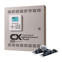
Low Voltage Control Diagrams shown in Figure 3 below are for use with Hubbell Building Automation Input Devices ONLY.
Diagrams may not apply to input devices from other manufacturers.
Figure 3 - Low Voltage Input Wiring Diagrams
Operating the panel
To operate the panel, do the following:
1. Connect the User Interface control ribbon cable to the User Interface Ribbon Cable Connector on the Mother Board
where shown in Figure 4. The User Interface control ribbon cable is supplied connected to the User Interface Module that
is attached to the panel door.
2. Connect the green ground jumper to the panel housing ground lug, labeled “GND” with the hardware provided. The green
ground jumper is supplied attached to the panel door.
3. Provide control power to the panel and restore power to the lighting circuits at the source circuit breakers. The panel will
take a few moments to initialize during which time the User Interface screen on the front of the panel door will initiate and
display the clock, date, and time zone un-programmed factory defaults. Inside the panel the Mother board power status
LED will show continuous “green”. The Relay board status LED will turn on “green” for approximately 2 seconds and then
go off.
4. Push, but do not hold the Relay Manual Control button on each relay card to operate each relay to test functionality. The
Relay State Status LED will turn on “red” when the relay is energized and be off when the relay is un-energized. The
panel is now fully functional and ready to control the lighting loads.
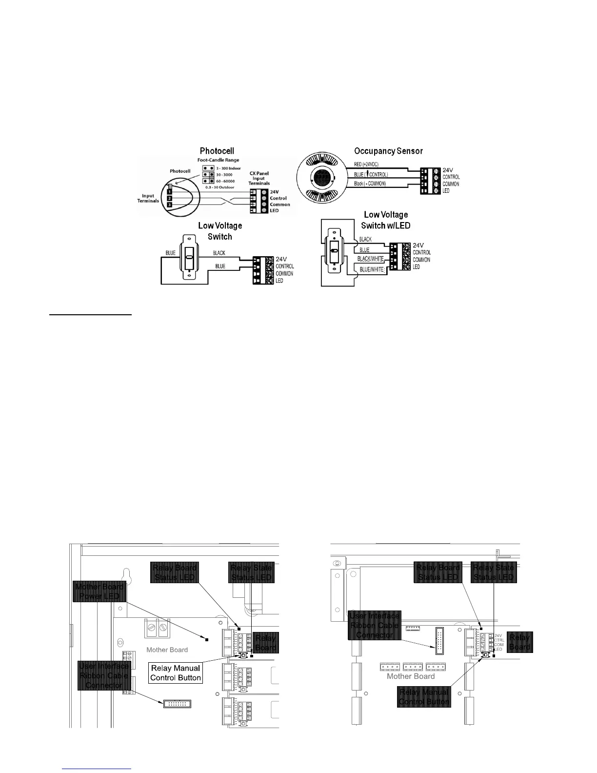
Figure 4 - Panel Start-Up Controls
CX04 and CX08 CX16 and CX24
 Loading...