uPPeR SnAP
-
Ring ReMoVAl
–
g900 SeRieS
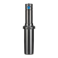
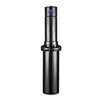
Prior to removal of the upper snap-ring assembly, the rubberized logo cap must be removed and the riser assembly
must be pressed below the snap-ring’s rubberized seal. If the procedure below is not followed, the upper snap-ring
assembly cannot be removed from the G900 Series rotors:
Remove the stainless screw from the center of the rubberized logo cap using a Phillips screwdriver (g 10). Prior to
removing the rubberized logo cap, note that the arrows on the logo indicate the position of the nozzles on the riser
assembly. As the rubberized logo cap is removed, note there is a protruding pin on the underside of the logo cap
(g 11). This pin is the alignment feature on the rubberized logo cap that must be inserted correctly during assembly
in order for the arrows on the rubberized logo cap to be positioned over the nozzles below. Note which hole the pin
ts into on top of the riser (g 12). Also note that the pin and hole locations are different for the G90 and G95 risers.
Once the rubberized logo cap is removed, use the heal on the palm of your hand to forcefully press the riser
assembly down (g 13) and below the rubberized wiper seal on the snap-ring assembly (g 14). When the rotor is
dry (without water within) more force is required. If sprinkler is installed and has been activated, the water acts to
lubricate the wiper making the procedure much easier.
FIG 10 FIG 11 FIG 12
FIG 13 FIG 14 FIG 15
FIG 16 FIG 17
8
 Loading...
