PReSSuRe RegulAToR RePlACeMenT
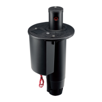
ToreplacethePressureRegulator,rstdisengagetheSolenoidandPilotValvefromtheangecompartment.This
action will create easier access to the Pressure Regulator. Next, notice the two tubes that are connected at the base
of the Pressure Regulator (g 147). The tube entering the center of the Pressure Regulator is the inlet and it comes
from the top tting in the Pilot Valve. The tube that is offset from the center is the outlet and it goes to the rotor’s
body wall. One of the TTS rotor’s valuable features is that the water discharged from the valve circuitry is vented into
the rotor’s body and then out the nozzles.
To replace the Pressure Regulator, use side-cutters or blade to make clean cuts in the tubing at points just before
they enter into the Pressure Regulator. Next, connect the inlet tube going into the center of the new Pressure Regula-
tor. To connect, pinch tube’s end with ngers in order to make the opening as round as possible. Place the end of
the tube to the Pressure Regulator’s center connection point then press and wiggle into position. Make sure the
tube goes in as far as possible. Next, connect the outlet tube going to the rotor’s body wall. If removed, attach the
SolenoidandPilotValvetotheangecompartment.Finally,insertPressureRegulatorintoanyconvenientavailable
locationwithintheangecompartment.
ATTACHing THe flAnge CoMPARTMenT lid
Takeamomentforanalchecktomakesurethatalloftheangecompartmentcomponentshavebeeninstalled
properly.PlacetheangecompartmentlidintopositionandaligntheSelectorCaptoitsholeinthelid.Pressthe
angecompartmentlidintopositionandsecurewiththestainlesssteelretainingscrews(g148).Finally,check
Selector Cap for free movement of the On-Off-Auto Feature.
If you have further questions after reviewing this manual, please contact Hunter’s Technical Services Department at
800-733-2823 and select option #3.
FIG 148FIG 147
53
 Loading...
