ConTRol Tubing ConneCTionS
–
C.o.M ModelS ConVeRTed To
HydRAuliC ConfiguRATion
Inhydraulicinstallations,theangecompartmentshouldbeusedtomaketheControlTubingconnectionstothe
rotor.Thisallowsfortubingconnections,pressuretestsandushingofthecontrollines-allwithoutdigging.
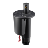
ConvertingC.O.M.modelstotheHydraulicconguration–Removethetwostainlesssteelscrewsandlifttheange
compartmentlidtoexposetheangecompartment.Findtheendofthe
1
⁄8inchtubingthatcomesintotheange
compartment from the bottom of the rotor (g 4). Check-O-Matic (“C”) versions of TTS rotors can be converted for
use in Normally Open Hydraulic systems by removing the end cap on the
1
⁄8inchtubing.Todoso,slidethe¼inch
tuberetainertowardstheendofthetube(g5).Then,pulltoremovetheendcapwithattached¼inchtuberetainer
from the brass connector tting (g 6).
Toconnectthe¼inchcontroltubefromthecontrollertotheTTSrotortubing,insert¼inchtubingfromcontroller
intothebottomoftheangecompartment.Nextslidethe¼inchtuberetainer(fromendcapsuppliedwithrotor)
ontothe¼inchControlTubing.Thenconnectthe¼inchControlTubingtotherotor’s
1
⁄8 inch Control Tubing by
pressingtogetheratthebrasstting.Finally,slidethe¼inchtuberetainertowardsthebrassttingtolockthe
tube in place.
FIG 4 FIG 5 FIG 6
6
 Loading...
