ConneCTing Solenoid To THe PiloT VAlVe
To ensure that the On-Off-Auto feature functions properly, follow the procedure outlined below. The TTS rotor’s
Solenoid has double-lead threads. If this procedure is not followed, the Solenoid can be attached to the Pilot Valve
180 degrees out of position. While the On-Off-Auto feature will function if connected out of position, it will function
much better if connected correctly.
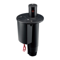
First,noticethatthereisaatsectionononesideoftheSolenoid(g137).This“at”isusedasareferencewhen
connectingtheSolenoidtothePilotValve.Next,noticethereisalsoaatsectionalongthesideofthePilotValveata
pointoppositeoftheuppertting.This“at”isthesecondreferencewhenconnectingtheSolenoidtothePilotValve.
With the gray Detent Ring attached to the bottom of the Solenoid, bring the Solenoid and the Pilot Valve together.
PriortoengagingtheSolenoidandPilotValvethreads,aligntheatsontheSolenoidandPilotValvethenpress
together. Prior to turning Solenoid clockwise, you must rst turn the Solenoid counter-clockwise 1/8th of a turn. This
action ensures that the correct rst thread on Solenoid engages the rst thread on the Pilot Valve. Now press the
Solenoid & Pilot Valve together while threading the Solenoid clockwise onto the Pilot Valve.
Next, the Solenoid must be placed in the Auto position. To do so, keep turning the Solenoid clockwise onto the Pilot
Valve until it stops (bottoms out). Do not tighten! Then, turn the Solenoid counter-clockwise until you feel the rst
Detent Ring click (g 138). This is the Auto position.
To check for proper alignment, position the connected Solenoid and Pilot Valve assembly in your hand so you are
lookingatthetop.Next,rotatetheSolenoidandPilotValveassemblyuntilthe“at”ontheSolenoidisatthe12:00
position(donotunthreadSolenoidfromPilotValve).WiththeSolenoid’satinthe12:00position,thePilotvalve’s
ttings should be at the 3:00 position. If the ttings are not at the 3:00 position, disconnect and repeat the procedure.
FIG 137 FIG 138
48
 Loading...
