To remove the snap-ring assembly, hold Snap-ring Tool vertical over the rotor’s upper snap-ring area. Align the metal
end of the snap-ring tool to the indicator on the snap-ring’s rubberized wiper seal (g 15). Use the palm of the other
handtodrivethetooldownward&throughtherubberizedmembrane(g16).Toolshouldpenetrateabout¼inch
into the snap-ring assembly. While holding the tool within the snap-ring, press the tool’s handle downward and away
from the center of the rotor. As the tool is pressed downward, the snap-ring will lift from the rotor. While using the
tool to hold the snap-ring in this elevated position, use the other hand to pull the snap-ring from the rotor (g 17). If
the snap-ring’s rubberized wiper seal appears to be the only part that is lifting, the tool has not penetrated into the
snap-ring far enough.
RiSeR ReMoVAl
–
All ModelS
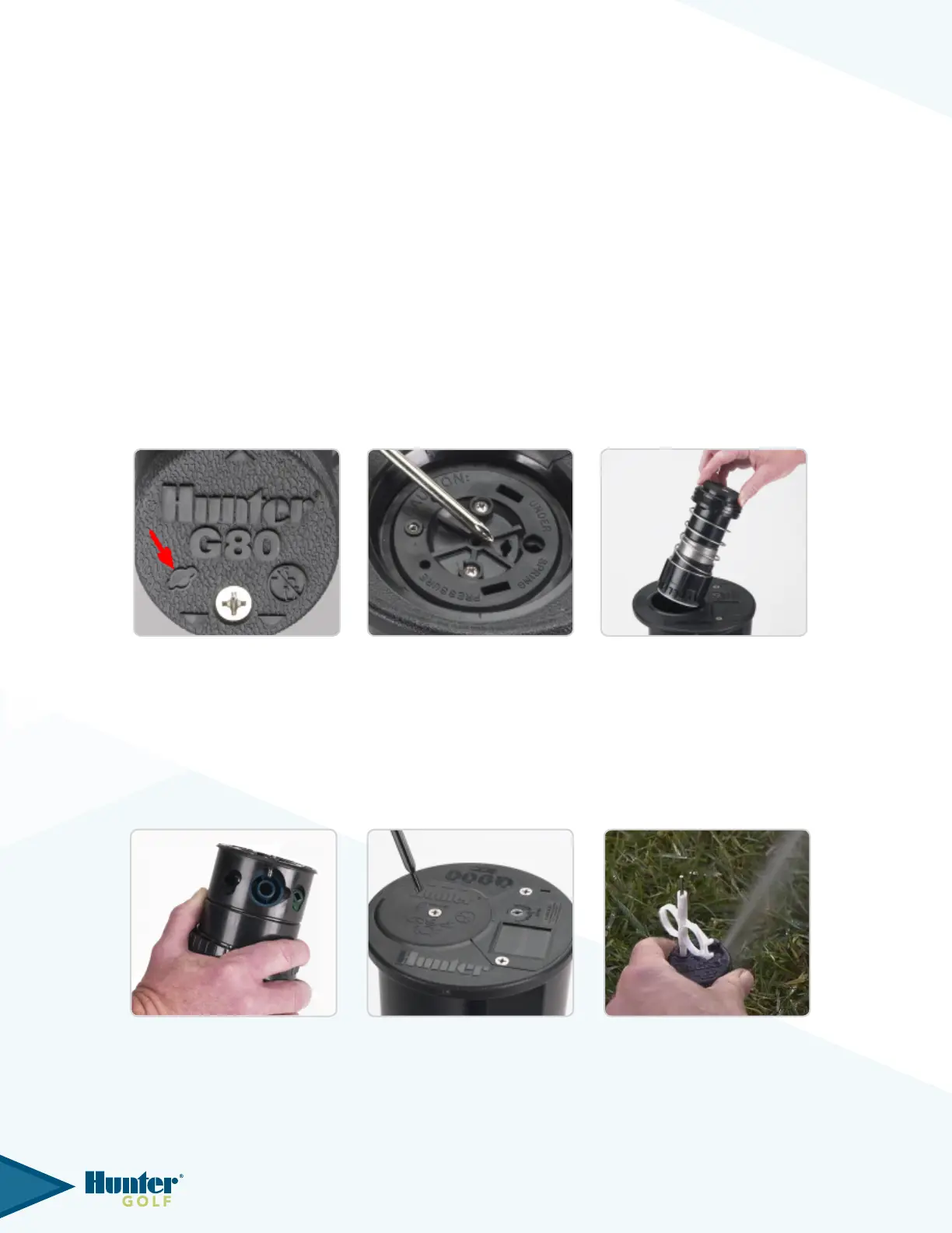
To remove the riser assembly, rst remove the upper snap ring as outlined above. Insert the Hunter Wrench, T-Handle
ToolortipoftheSnapRingtoolintotheriser’sliftsocket,turn¼turnandlifttheriserfromtherotor’sbody.Thelift
socket for G870, G875 and G880 models is protected by a rubberized membrane on the rubberized logo cap and can
be located by nding the raised line depiction of the socket’s shape (g 18). G990 and G995 risers have a removable
rubberized logo cap so the lift up socket is accessed after removing the logo cap, directly on top of the riser (g 19).
In some cases, the riser can simply be pulled from the rotor’s body by hand once the upper snap-ring assembly is
removed (g 20).
ARC AdjuSTMenT PRePARATion
–
g35, g75 & g95 PART
-
CiRCle RiSeRS
All Hunter adjustable arc rotors have a xed stop on the right side of the arc and an adjustable stop on the left side of
the arc. Arc adjustments can be made with the riser in hand or, after installation with the rotor not activated or, while
the rotor is in operation. For convenience of installation, new rotors from the factory are set to approximately
180 degrees and the long-range nozzle is positioned to the right x side of the arc.
Before setting the arc, it is necessary to rst establish where the right side xed arc stop is located:
FIG 21 FIG 22 FIG 23
FIG 18 FIG 19 FIG 20
9