Solenoid ConneCTionS
–
eleCTRiC ViH ModelS
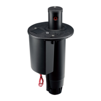
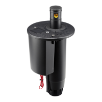
TTS Electric Valve-In-Head models have solenoid lead wires protruding from the rotor’s body in the traditional
manner. Controller eld wires can be connected to the rotor, using the specied watertight wiring connectors, at this
sub-surface position. If specied or requested otherwise, the solenoid lead wires and controller eld wires can be
pulledupintotherotor’sangecompartmentwheretheinitialconnectionscanbemade(recommended).Regardless
oftheinitialconnectionpoint,futuresolenoidrepairconnectionscanbemadewithintheangecompartment.(see
Solenoid Servicing later in this manual)
Caution! Whenconnectingsolenoidleadsoutsideoftheangecompartment,DONOTpullsolenoidleads
downward in an attempt to provide more exposed solenoid wire. Electric TTS rotors REQUIRE slack in solenoid wiring
withintheangecompartmenttofacilitateservicingofthepilotvalveandsolenoid.Removingtheslackcanlimit
movement of the On-Auto-Off selector and require cutting of solenoid wires to service pilot valve and/or solenoid.
Recommended Wiring
Connections
RECOMMENDED WIRING CONNECTIONS
DO NOT PULL ON
SOLENOID LEAD WIRING
4
 Loading...
