47 48
Learn more. Visit hunterindustries.com/golf
SOLENOID, PILOT VALVE & REGULATOR SERVICING I TABLE OF CONTENTS
TABLE OF CONTENTS I SOLENOID, PILOT VALVE & REGULATOR SERVICING
SOLENOID, PILOT VALVE
& REGULATOR SERVICING
All Electric VIH Models
Caution! Electric valve-in-head rotors are connected to pressurized main or sub-main piping. This
pressurized piping must be depressurized before servicing the rotor. This rotor will activate (turn
on) if Solenoid is loosened or if Solenoid is removed or if Pilot Valve is removed or the supply
tubing is cut. High velocity water streams and ows are emitted from the rotor. Bodily injury can
occur if the water stream hits the face, eyes, ears or other body parts. Keep head and body parts
away from water stream. Wear proper eye protection and use the designated tools when servicing
these rotors. Whenever possible, keep head and body parts away from the top of the rotor.
TOOLS NEEDED
4
Phillips Screwdriver
4
Tubing Clamp, Locking Forceps or ¼” Tube Retainer
4
Flat Blade Screwdriver
4
Side Cutters (Dykes) or Blade Cutter
4
Snap Ring Tool - PN 052510
4
Hunter Wrench – PN 172000
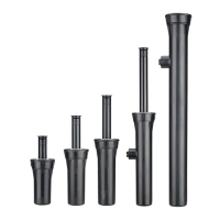
ACCESS TO FLANGE COMPARTMENT COMPONENTS
Using a Phillips screwdriver, remove the two stainless steel screws that retain the ange
compartment’s lid (FIGURE 124). A slot is located adjacent to the on-o-auto selector at the edge
of the ange lid. Use a bladed screwdriver or the tip of the snap ring tool to pry the ange lid up
(FIGURE 125). Set the ange lid and screws aside. Factory installed ange compartment lids have
a large recessed area that can be used for the application of yardage marker placards (FIGURE
126). An optional ange compartment lid is available with a raised area for paint-lled engraving
of the yardage marker (FIGURE 127). This optional version is available only as a replacement part.
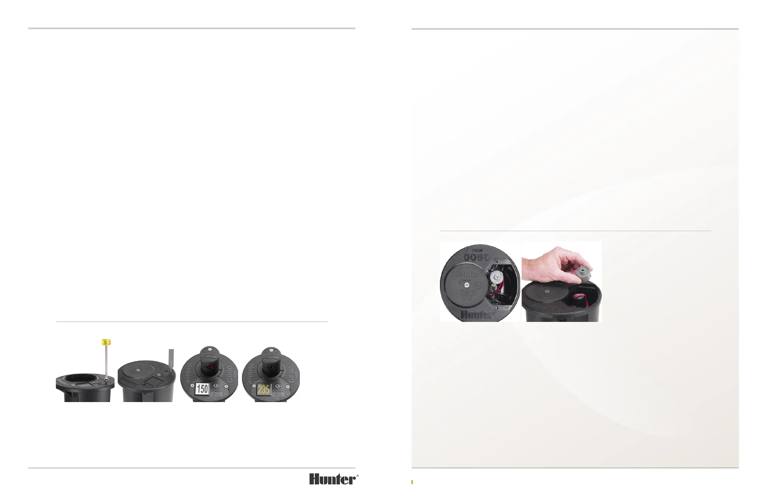
With the ange compartment lid removed and
prior to disassembly, take time to note the
orientation of the various components within
the ange compartment (FIGURE 128). This will
be valuable later for reference during nal
assembly. In particular, notice:
• How the solenoid wires fold over the top and to the at side of the solenoid
• How, in the Auto position, the at on the side of the solenoid faces to the outside
• How the pilot valve’s ttings and connected tubing point in a specic direction
• How the pressure regulator is tucked into position within the compartment
Selector Cap Removal
The Selector Cap turns the Solenoid when the
user changes the ON-AUTO-OFF settings. Under
normal operating conditions, the Selector Cap
should not need replacement. The Selector Cap
can become damaged if the incorrect tool
is used to make ON-AUTO-OFF selection
adjustments. Prior to removing the Selector Cap,
notice that the Solenoid wires run over the top
of the Solenoid and out of the Selector Cap on
the side of the Solenoid that has the at surface.
Also note that the Solenoid wires are positioned
side-by-side and not twisted. To remove the
Selector Cap, simply li it up and away from the
Solenoid (FIGURE 129).
FIGURE 124 FIGURE 125 FIGURE 126 FIGURE 127
FIGURE 128 FIGURE 129