49 50
Learn more. Visit hunterindustries.com/golf
TABLE OF CONTENTS I SOLENOID & PILOT VALVE ASSEMBLY REMOVAL
SOLENOID & PILOT VALVE ASSEMBLY REMOVAL I TABLE OF CONTENTS
SOLENOID & PILOT VALVE ASSEMBLY REMOVAL
In order to work on the Solenoid or the Pilot Valve, it is rst necessary to remove the connected
Solenoid and Pilot Valve assembly from the ange compartment. Prior to removal, take note of
the orientation of the ttings and tubing that are attached to the Pilot Valve. This will help with
nal assembly later.
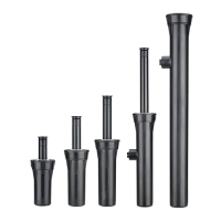
To remove the Solenoid and Pilot Valve from the ange compartment, grab the Solenoid and
wiggle it back and forth while liing upwards (FIGURE 130). Pull the Solenoid and Pilot Valve
assembly up and on top of the rotor’s ange (FIGURE 131).
SOLENOID SERVICING AND REPLACEMENT
Preventing Sprinkler Activation –
See the warning above regarding rotor activation when Solenoid is loosened or removed.
There are three ways to prevent activation of the rotor when the Solenoid is removed from the
Pilot Valve:
The best and most eective way is to shut down the main line or the sub-main line water
supply to the rotor that is being serviced. Be aware that residual pressure may reside in the
system piping even aer that valve has been closed. To purge residual pressure, activate a rotor or
quick-coupler near to the rotor being serviced or, move the selector to the manual On position.
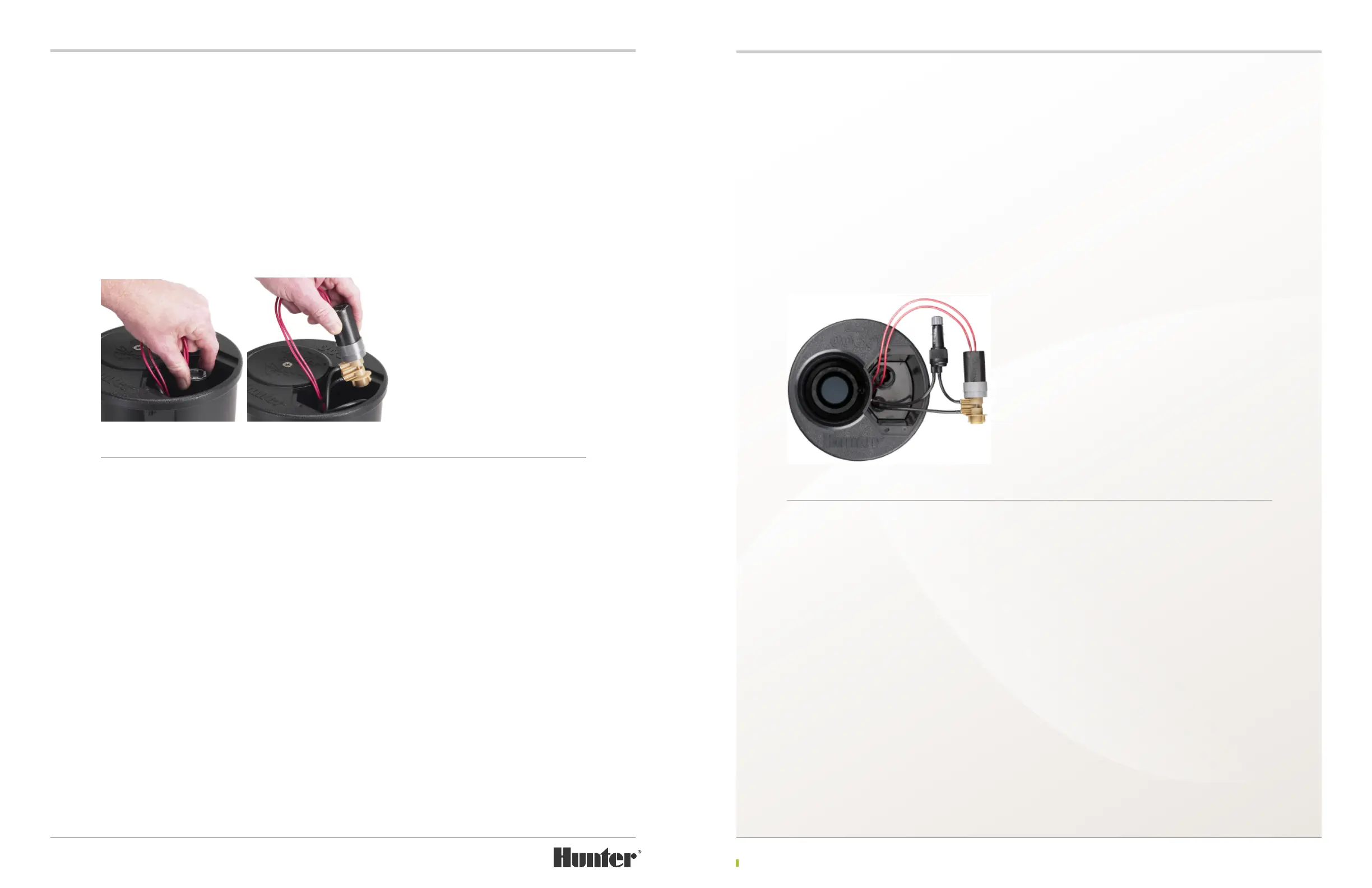
A tubing clamp or locking forceps tool can be used to pinch the supply tube going into the Pilot
Valve. The pressurized supply tube runs from the inlet area of the rotor and up into the ange
compartment, then is directly connected to the bottom tting on the Pilot Valve (FIGURE 132).
Caution – care needs to be taken and an appropriate tool used to avoid damaging the tubing as it
is clamped closed. A leaking supply tube will cause the rotor to weep water while deactivated.
A ¼” tubing retainer can be used to pinch the
supply tube going into the Pilot Valve. Note that
the tubing used within the TTS rotor’s ange
compartment is ⅛” tubing, NOT ¼” tubing. To
do so, bend the supply tubing together and slide
the tube retainer over the bent end to hold the
tubing closed. The pressurized supply tube
runs from the inlet area of the rotor and up
into the ange compartment, then is directly
connected to the bottom tting on the Pilot
Valve (FIGURE 132).
Caution – care needs to be taken so as to avoid damaging the tubing as it is bent closed. This
procedure is not recommended in cold weather conditions. A leaking supply tube will cause the
rotor to weep water while deactivated.
Separate the Solenoid from the Pilot Valve -
Remove the Solenoid from Pilot Valve with
counter-clockwise turns. Pull to separate the
Solenoid from the Pilot Valve (FIGURE 133). The
gray plastic part at the base of the Solenoid
is called the Detent Ring. When the Solenoid
is attached to the Pilot Valve, the Detent Ring
interacts with the Pilot Valve to create the Auto
position’s detent (the stopping point when
moving the Selector Cap to the Auto position).
Under normal operating conditions, the Detent
Ring will not need replacement. If the solenoid
needs to be replaced, it will also be necessary
to replace the detent ring.
Solenoid Servicing – The Plunger assembly
and the rubberized Seat-Seal are serviceable on
Hunter Solenoids. To replace a worn or damaged
rubberized Seat-Seal, simply pull the old one
o and press the new one into position on the
Solenoid’s Plunger. Since a worn or damaged
rubberized Seat-Seal can cause the rotor to
weep water when the rotor is deactivated, it is
highly recommended that the rubberized Seat-
Seal be replaced whenever servicing the Plunger
assembly.
FIGURE 130 FIGURE 131
FIGURE 132