Underwater Gear
6.3
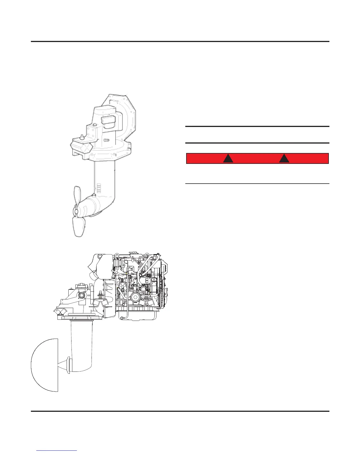
The 40HP engine (see the Engines and Transmissions
chapter of this manual for additional details about the
engine) utilizes the saildrive method of propulsion. For
reference purposes, Fig. 6.5 illustrates the sail drive leg
and gear assembly and Fig. 6.6 illustrates the full sail
drive/engine assembly.
Figure 6.5
Figure 6.6
The saildrive has some advantages over the traditional
shaft drive. It is quieter with less vibration and it offers
higher efficiency due to the foil shaped sections of the
drive leg and lack of any shaft angle.
It is extremely important to regularly check the sacrifi
-
cial zinc anode attached to your saildrive. The anode
provides protection against galvanic corrosion. Refer to
the manufacturer’s OEM manual for a complete listing
of regular maintenance items and schedules for your
saildrive.
6.2 Steering Components
Keep clear of moving steering parts at all times. Pro-
tect moving parts from impact during normal use.
6.2.1 Steering System
The steering system of your boat consists of a steering
wheel, pedestal (with rack and pinion), output lever, drag-
link, tiller arm, rudder assembly and optional autopilot
(Fig. 6.7). Movement of the steering wheel is reflected in
the rotation of the output lever located below the pedestal
as translated by the rack and pinion gearing within the
pedestal. The rotation of the output lever is transferred
to the tiller arm by connection through the draglink. This
assembly concludes with the rudder post bolted to the til
-
ler arm. Thus, movement of the steering wheel translates
to the rotation or swing of the rudder.
Also note that the opposite side of the tiller arm is also
fastened to a drag-link. This drag-link is connected to
the motor of the optional autopilot (also pictured is the
autopilot’s rudder reference module).
NOTE: Please refer to the steering OEM manual for specific
details and maintenance specifications.
6.2.2 Rudders
The rudder blade (see Fig. 6.8) is fabricated with a stain-
less steel internal grid structure surrounded by foam
and fiberglass. The rudder bearings are self lubricat
-
ing. Inspect your rudder for free and smooth movement
between rudder stock and bearings.
Obviously, your steering system is a critical component
aboard your boat. However, all boat operator’s should
Underwater Gear
6.3