Underwater Gear
6.6
exhaust or the venting of tanks.
Refer to Figures 6.18 and 6.19 for thru-hull locations.
Later chapters in this manual will go into further detail
about the various systems that will incorporate these fit-
tings.
6.4 Monitoring Equipment
The optional electronics package installed on your boat
will vary boat to boat. However, all Hunter’s will have a
transducer (Fig. 6.11) installed below the waterline. In
general, the transducer is the sensing device which pro-
vides desired information to your electronic equipment,
such as depth, speed, temp, etc. Refer to the electronics
OEM manuals for specific details about your equipment.
The transducer is located beneath the compression post
floor panel in the v-berth.
Figure 6.13
6.5 Anchoring and Optional Windlass
A complete anchoring assembly includes the anchor, bow
roller (also a secondary bow roller), anchor rode/chain,
windlass, anchor locker and padeye.
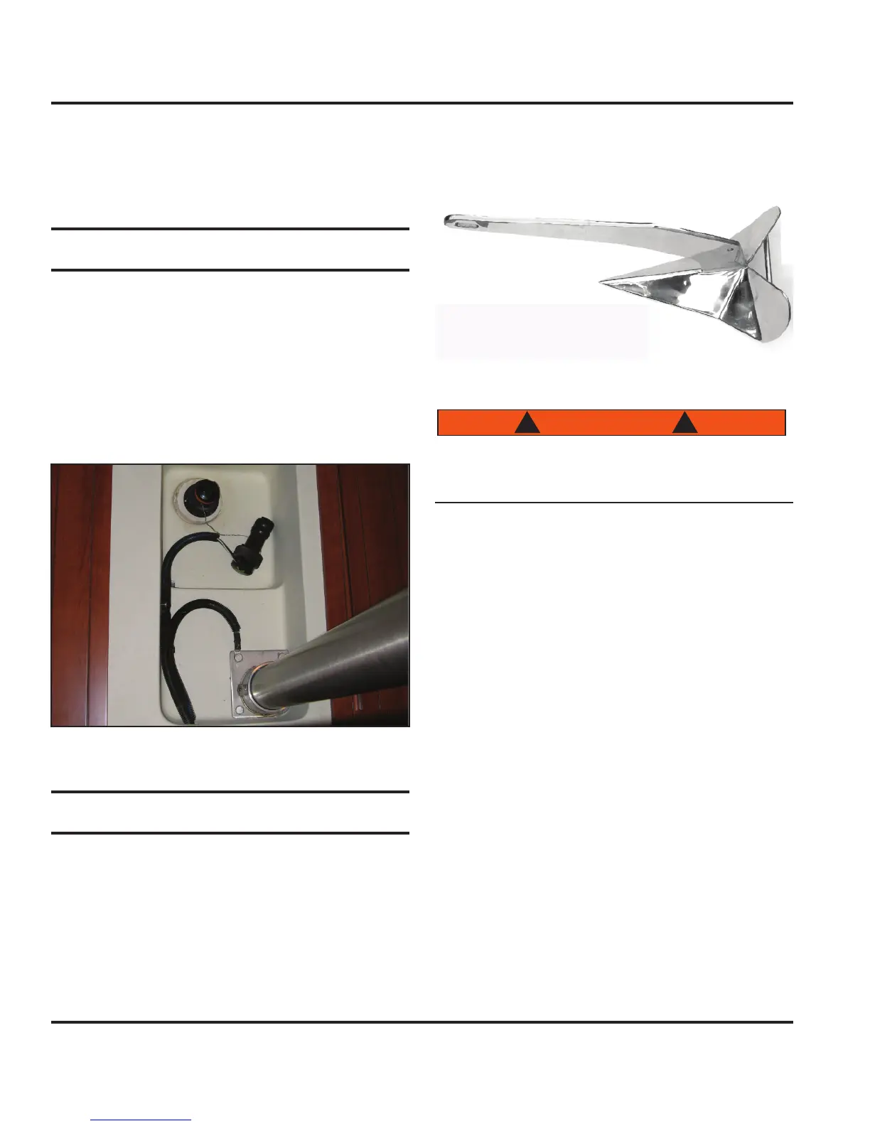
6.5.1 Anchor
The anchor option available on your boat includes a 22
lb. delta anchor (see example Fig. 6.14) with 100 feet of
chain. This anchor was selected based on your boat’s
size and weight under normal anchoring conditions. This
style is effective with a variety of sea beds and remains
stable under a variety of tide and wind conditions.
Figure 6.14
Anchoring in unusual water and/or weather condi-
tions will require additional precautions. Consult an
approved guide for suggestions.
6.5.2 Windlass
The windlass (see Fig. 6.15) facilitates the anchoring
of your boat by automatically raising and lowering the
anchor. To operate the windlass, the Anchor breaker
switch, located on the Battery Switch Panel, must be
set (refer to the DC Electrical Systems chapter of this
manual).
6.5.2.1 Lowering the Anchor
Turn power on to the windlass at the Battery Switch
Panel (see DC System chapter in this manual).
Set the Anchor breaker (see DC System chapter in
this manual).
Rotate the anchor stop flapper to free up the anchor
chain.
Lift the protective cap from the windlass foot switch
located on the bow near the anchorwell and depress the
down switch (Fig. 6.16).
Note: “Bump” the switch until the anchor clears the
anchor roller and hull before letting anchor down
freely or it may rock back and forth and strike the hull.
1.
2.
3.