DC Electric Systems
7.2
Figure 7.1
7.2 DC Power Supply and Control
Components
Please refer to Fig. 7.18 for the basic power supply
equipment and component layouts as reference for this
section.
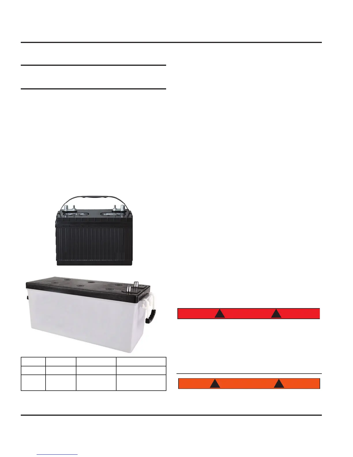
7.2.1 Batteries
The batteries speced for your boat have been selected
for their ability to furnish starting power based on engine
requirements, as well as their ability to power the DC
system components (or house). We recommend AGM
(absorbed glass mat) batteries (see Fig. 7.2 for battery
specs).
Size Volts Function Qty
24 12 START 1
4D 12 HOUSE
1
(+1 Optional)
Figure. 7.2
The DC system derives its power from two separate bat-
tery banks: start and house batteries. The house side
is further prewired for an additional 4D battery (doubling
the amp hour capacity). Batteries are located in the nav
station and galley bilges. One house battery can be
accessed from under the floor panel inboard of the nav
station seat and the other under the floor panel aft of the
galley sink. The start battery can be accessed under the
floor panel aft of the 4D galley battery location.
Both banks are wired to the Battery Switch Panel (BSP)
(Fig. 7.3). The batteries supply power first to the battery
selector switches on the BSP then to the 12 Volt DC
Panel (see Fig. 7.10), which distributes power to other
subpanels and systems. (Some equipment is immedi-
ately energized from the batteries, i.e. main bilge pump.)
The negative terminal of both banks are attached to
the DC ground connection on the engine. This system,
known as the negative ground system, is the approved
system for marine DC electrical systems. The battery
wiring system has two color coded wires: yellow - nega-
tive (ground), and red - positive.
To avoid explosions, do not use jumper cables and
a booster battery to start the engine. If batteries are
dead, recharge them with the optional battery charger (if
installed) (discussed later), optional inverter (if installed)
(discussed later) or remove and recharge on shore.
Batteries produce hydrogen and oxygen gasses when
being charged. If ventilation is poor, these explosive
gasses escape through the vent/fill caps and may form
an explosive atmosphere around the battery. This gas
may remain around the battery for several hours after
charging. Sparks or flame can ignite the gas and cause
an explosion.
Batteries contain Sulfuric Acid and can cause severe
personal injury if mishandled.
Avoid contact with eyes, skin, or clothing. In case of
contact, flush with water at least 15 minutes.
If swallowed, drink large quantities of water or Milk
of Magnesia, beaten egg, or vegetable oil and seek
medical attention immediately.
Charging batteries produce gasses which can ex-
plode if ignited.