DC Electric Systems
7.10
transom garage (refer to the Waste Systems chapter in
this manual for additional information on the blower).
Fuel fumes in the engine compartment can explode.
Before working on electrical wiring, ventilate
engine bay and disconnect battery cables to
prevent sparks.
7.3.1.10 LPG Panel Breaker
The breaker for the LPG panel protects the panel from a
power fault. The 5 amp pop-out breaker is labeled “LPG
Panel”. The LPG panel is an on/off switch allowing for
remote control of LPG flow to the stove.
Please see the Fuel chapter in this manual for information
on LPG hazards and use of the LPG system.
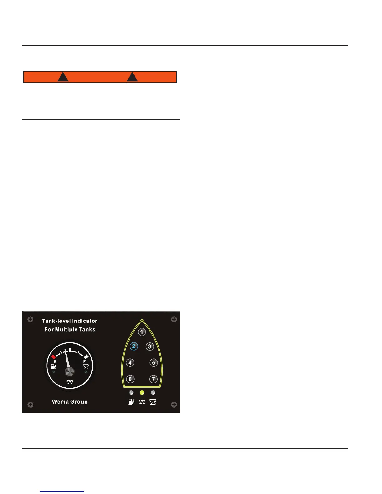
7.3.1.11 Tank Monitoring Panel
The monitoring of the fresh water and waste tanks is
combined on a single panel (Fig. 7.16). This multi-tank
monitoring panel is located on the hull panel of the nav
station near the chart table light. Labels will be placed
on the panel to map each tank to a number. To check
the status of a tank, press the corresponding tank number
to illuminate the tank type indicator which activate the
gauge on the left.
Once the DC Panel is energized, the tank monitor panel
is also energized. A 5 amp pop-out breaker labeled “Tank
Monitor” protects the panel circuitry from a power fault.
Figure 7.16
7.3.1.12 Watermaker Breaker
Not used.
7.3.1.13 Fuel Pump
Not used. The fuel pump is part of the engine assem-
bly.
7.3.1.14 DVSR Module
The DVSR (Digital Voltage Sensing Relay) is a fully auto-
matic subsystem within the DC system and requires no
interaction by the boat operator and is only mentioned to
explain its purpose.
The DVSR allows charging of two independent battery
banks from a single charging source. When the voltage
on the start battery rises to a charged level, the DVSR
engages and allows the 2nd battery to charge. When
charging stops and voltage falls, the DVSR will disen-
gage, isolating the two batteries from each other. Dual
sensing functionality enables the sensing of two battery
banks, allowing two way charging.
7.3.1.15 Parallel Charge Circuit
Not used.
7.3.1.16 Digital Engine Panel
Not used.
7.3.1.17 Start Battery Test Breaker
The digital volt meter display in the upper right hand cor-
ner of the DC Panel is immediately energized from the
battery banks to provide feedback on the battery status.
A 5 amp pop-out breaker exists on the Battery Switch
Panel labeled “Start Battery Test” to protect the battery
banks from a power fault originating from the meter com-
ponent.
7.3.1.18 Oil Changer Breaker
The purpose of the optional oil changer component is to
allow automatic oil draining and filling of boat and genera-
tor engines (Fig. 7.17). A 15 amp pop-out breaker exists
on the Battery Switch Panel labeled “Oil Changer” to
protect the oil changer from a power fault.
7.3.1.19 Spare Breaker Positions
The BSP has spare positions available for the installation