DC Electric Systems
7.12
Boat based visibility lighting
7.3.2.5.1 Safety and Navigational Lighting - Running
Lights, Anchor Light & Steaming Light Breakers
The navigational lighting consists of the following indi-
vidual light components (see also the Boating Safety
chapter of this manual for additional information on navi-
gational lighting):
Running lights - the standard starboard (green), port
(red) lights and stern (white) lights located on the
deck
Anchor light - the 360 degree light located on the top
of the mast
Steaming light - the 225 degree light located on
the forward mast near the upper shroud spreader
(see the Sails & Rigging chapter in this manual for
spreader details)
A 5 amp switch breaker provides power to the running
lights. It is labeled “Running Lights” on the panel and
protects this system from a power fault.
Control of the anchor light and steaming light is through
a vertical 3-position toggle switch. Setting the switch in
the up position will illuminate the anchor light; middle
position is off; down position will illuminate the steaming
light. When either light is illuminated, an LED light on
the toggle switch will illuminate to indicate an energized
system. A 5 amp pop-out breaker located to the left of
the toggle switch protects the anchor light/steaming light
circuitry from a power fault.
The nav light configuration will depend on the status of
the boat at night:
Anchored - anchor light only
Under sail - running lights and steaming light
Under power - running lights and anchor light
7.3.2.5.2 Boat Based Visibility Lighting - Deck Light
& Cabin Light Breakers
The deck light, located half way up the mast, provides
foredeck illumination for safety and convenience. It
is controlled by a 5 amp switch breaker labeled “Deck
Lights” on the panel and protects this circuitry from a
power fault.
Cabin lights, courtesy lights and optional arch speaker
pod light are all energized once the DC panel is ener-
2.
1.
2.
3.
1.
2.
3.
gized. Circuitry for these lights are grouped into two 20
amp pop-out breakers labeled “Cabin Lights” which pro-
tect these systems from a power fault.
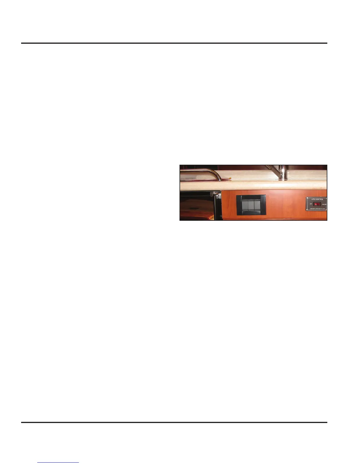
Individual wall or fixture switches allow lights on/off. One
3-switch wall light plate (Fig. 7.18) exists in the galley
and is located on the sink cabinet face. The left switch
controls the 3” main salon lights. The middle switch
controls the 3” galley lights. The right switch controls the
dish rack mini light and fan, located in the forward upper
galley cabinet.
The balance of the interior light fixtures (also cockpit
storage and optional arch speaker pod light) have on/off
switches on the fixture. Refer to Figure 7.20 for light fix-
ture location and details.
Figure 7.18
7.3.2.6 Fresh Water Pump Breaker
This 10 amp switch breaker controls power to the fresh
water pump. It is labeled “Water Pump” on the DC Panel
and protects it from a power fault. The water pump
pressurizes the fresh water system (refer to the Water
Systems chapter in this manual for additional details).
NOTE: Consult the pump manufacturers’ OEM manual for
pump operation, care and maintenance.
7.3.2.7 GPS/Chartplotter Switch/Breaker
This 10 amp switch breaker controls power to the optional
chartplotter ( wide-screen display). It is labeled “GPS” on
the panel and protects the chartplotter from a power fault.
The GPS is generally bundled with the chartplotter (with
or without radar).
NOTE: Consult the chartplotter manufacturers’ OEM manual
for instrument operation, care and maintenance.
7.3.2.8 Autopilot/Instruments Switch/Breaker
This 25 amp switch breaker controls power to the stan-