MAINTENANCE WORK ON CHASSIS AND ENGINE
- 34 -
ENGLISH
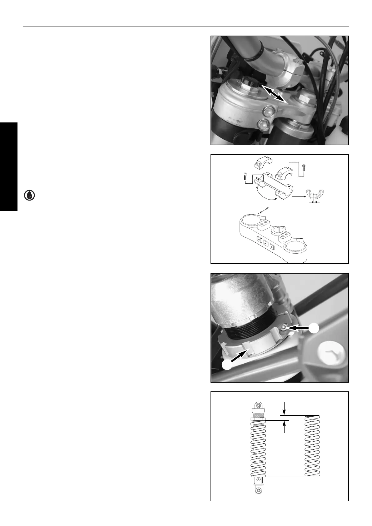
HOW TO CHANGE THE HANDLEBAR POSITION
The handlebar position can be readjusted by 22 mm. Thus, you can put
the handlebar in the position that is the most convenient for you. The upper
triple clamp (1) includes 2 bores arranged at a distance of 15 mm (0.6 in)
from one another. The bores at the handlebar support (2) are offset from
the center by 3.5 mm (0.13 in). Accordingly, you can mount the handle-
bar in 4 different positions.
For this purpose, remove screws (3) of the handlebar clamps and screws
(4) of the handlebar support. Position the handlebar support, and tighten
screws (4) to 40 Nm. Mount handlebar and handlebar clamps, and tigh-
ten screws (3) to 20 Nm. The gap between the handlebar support and
the handlebar clamps should be the same in the front and in the rear.
WARNING: The screws (4) must be secured with Loctite 243.
CHANGING THE SPRING PRELOADING OF THE
SHOCK ABSORBER
The spring preload can be changed by turning the adjusting ring (5). For
this purpose, you should dismount the shock absorber and clean it
thoroughly.
NOTE:
– Before changing the spring preload note down the basic setting, e.g.
how many threads are visible above the adjusting ring.
– One rotation of the adjusting ring (5) changes the spring pretension
by approximately 1.75 mm (0.07 in).
Loosen the clamping screw (6) and use the hook wrench contained in the
vehicle tool set to turn the adjusting ring as desired. Turning it counter-
clockwise will reduce the preload, turning it clockwise will increasethe
preload.
After readjusting the clamping screw (6), tighten it to 8 Nm.
ADJUSTMENT VALUES - SPRING PRELOAD (A)
minimum preload . . . . . . . . . . . . . . . . . . . . . . . . . . . . . . . . . . . . . .4 mm
STANDARD PRELOAD (FC 450,550) . . . . . . . . . . . . . . . . . . . . . .5 mm
STANDARD PRELOAD (FE 450,501,550,650) . . . . . . . . . . . . . . .5 mm
STANDARD PRELOAD (FS 450,650) . . . . . . . . . . . . . . . . . . . . .11 mm
maximum preload . . . . . . . . . . . . . . . . . . . . . . . . . . . . . . . . . . . .12 mm
1
2
3
4
15 mm
3,5 mm
A
5
6