2.2
PLC 100 CONTROL SYSTEM
OPERATION OVERVIEW
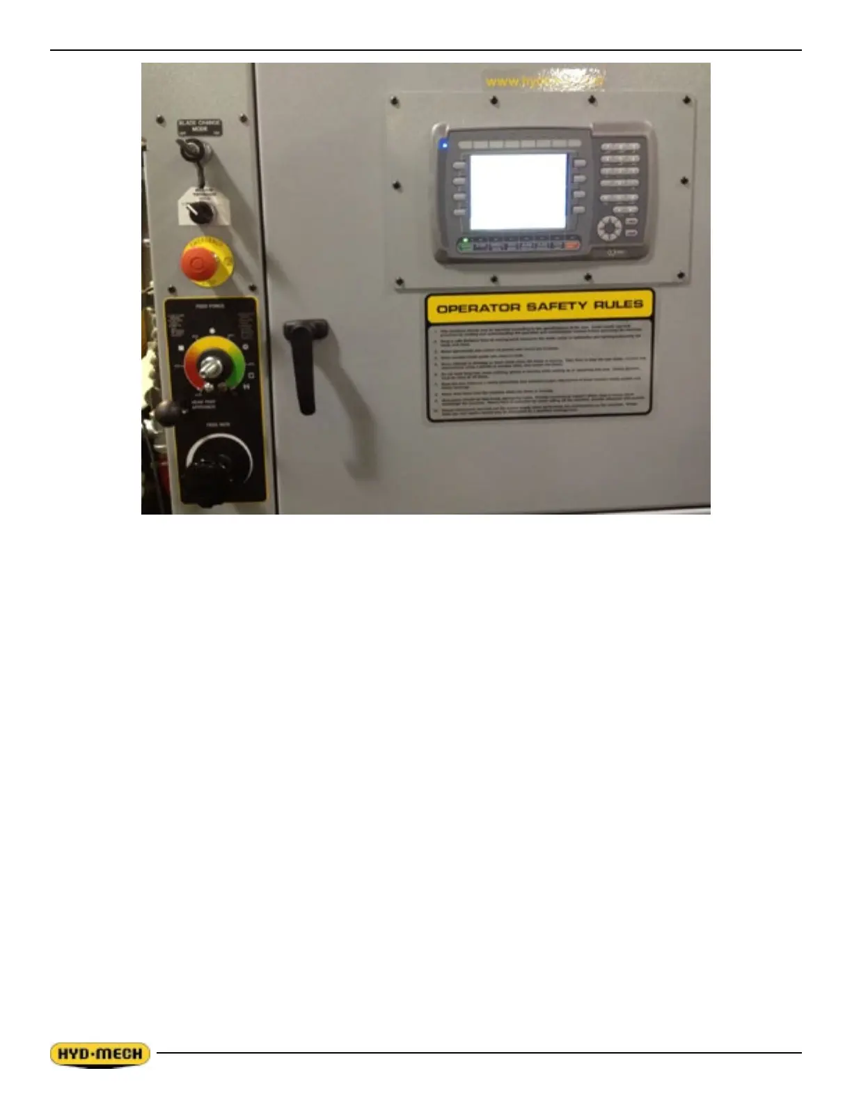
The PLC is a programmable logic controller that allows the operator to run the machine in both manual and automatic
modes.
All of the machine functions are also controlled from the PLC operator interface. There are four function buttons on
either side and eight function buttons below the display. The functions of the buttons below the screen are labeled on the
buttons themselves. The functions of the buttons to the left and right and the middle six buttons below the display are
indicated on the display in a coloured box immediately beside the button. The far left and right buttons below the display
are permanently labeled.
NOTE:
1. THE FUNCTION OF THE BUTTONS LABELED ON THE DISPLAY MAY CHANGE DEPENDING ON THE
SCREEN MODE BEING DISPLAYED.
2. ALL FUNCTIONS ARE NOT DISPLAYED ALL THE TIME. ADDITIONAL FUNCTIONS MAY BE ACCESSED BY
PRESSING THE FUNCTION BUTTON LABELED NEXT (IF DISPLAYED).
There is also a numeric keypad and a set of navigation keys to the right of the display. All of these as well as the
EMERGENCY STOP button detailed descriptions follow.
To power up the control panel, the EMERGENCY STOP button must be pulled out. The display screen will scroll through
several screens and nally display in MANUAL MODE. Once the control panel has power, the MACHINE START key
must be pressed to start the hydraulic system. Now all of the controls have been activated.
In MANUAL MODE, the operator has the ability to execute a single cut utilizing a pre-programmed SINGLE CUT MODE.
In AUTOMATIC MODE, the PLC has the capacity to program and store 999 jobs. Designated job numbers can be
programmed for the quantity required (maximum 99 pieces). Piece lengths range from 0” to 214” (5436 mm). Jobs can
be run individually or in a QUEUE, which allows a maximum of 5 jobs to run consecutively.
 Loading...