7.1
SECTION 7 - OPTIONAL EQUIPMENT
VARIABLE VISE PRESSURE KNOB
This knob is used to adjust the force applied to the work piece by the vises and bundling clamps. Lower force can avoid
deforming the work piece when cutting light structurals and tubes. Clockwise knob rotation increases clamping force. The
adjustment range is as follows.
Limit Gauge Indication Vise Force Clamp Force
Maximum 700 psi 1800 lbs 450 lbs
Minimum * 200 psi 600 lbs 150 lbs
* Lower pressure may result in erratic vise movement.
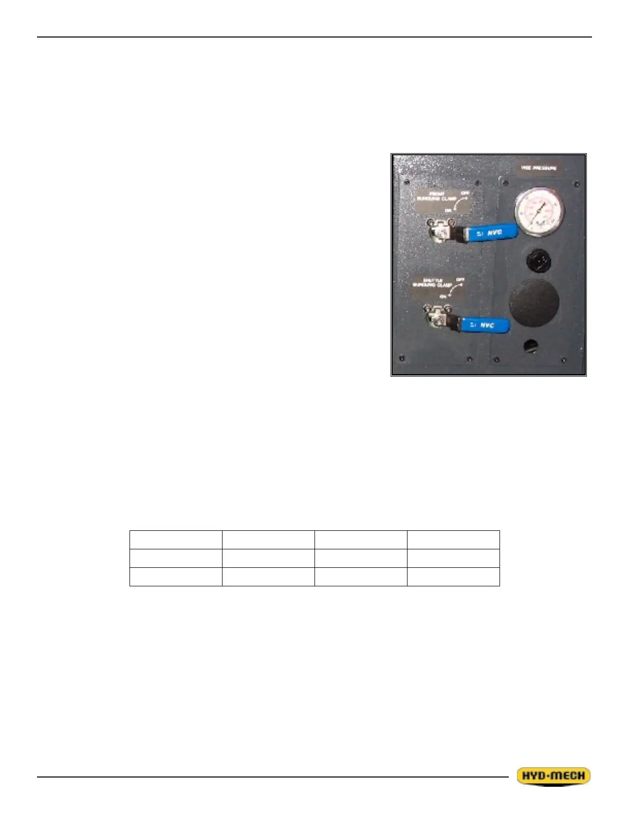
BUNDLING CLAMP VALVES
The bundling clamps can be used to supplement the front and shuttle vises
by clamping down on the work piece from above. As the name implies,
they are particularly used to clamp work pieces made of bundles of smaller
material.
For simple, non-bundled work pieces, the bundling clamps are not usually
needed.
Each bundling clamp has its own control valve. When the control valve
lever is positioned horizontally the bundling clamp is locked in its current
position. When the valve lever is vertical, the bundling clamp will move
open and shut with its associated vise.
VISE and BUNDLING CLAMP SPEED ADJUSTMENT
Vise and bundling clamp speed is factory preset to synchronize movement
of both clamps. The tuning valves are located next to the plate holding the
bundling control valves. Valves can be accessed through the hydraulic power pack door opening. Information on valve
adjustment is provided on the hydraulic plumbing diagram in Section 5.
FOR OPTIONAL ASSEMBLY DRAWINGS SEE PDF ON ATTACHED CD