7--9
92
Adjustments
Machine working pressures
This section describes the procedures to change the vice and head operating
pressures. Both adjustments strongly depend on the material type being pro-
cessed.
Thevicelockingpressurecanbesetifthematerialcouldbestrainedorcouldbe
quite unstable while cutting.
The head lowering speed can be set by a flow adjuster on the control console.
Hydraulic pressure
Both vice and head pressures can be adjusted by the power packs.
Both the pneumatic and hydraulic vices have a maximum travel of 8 mm. This
means that after positioning the workpiece on the work table and before start-
ing the cycle, the moving jaw must be positioned to within 2÷3mmofthe
workpiece as previously described in Chapter 5.
The operating pressures (shearing vice and cutting head) can be adjusted by the
max. pressure adjusting valve.
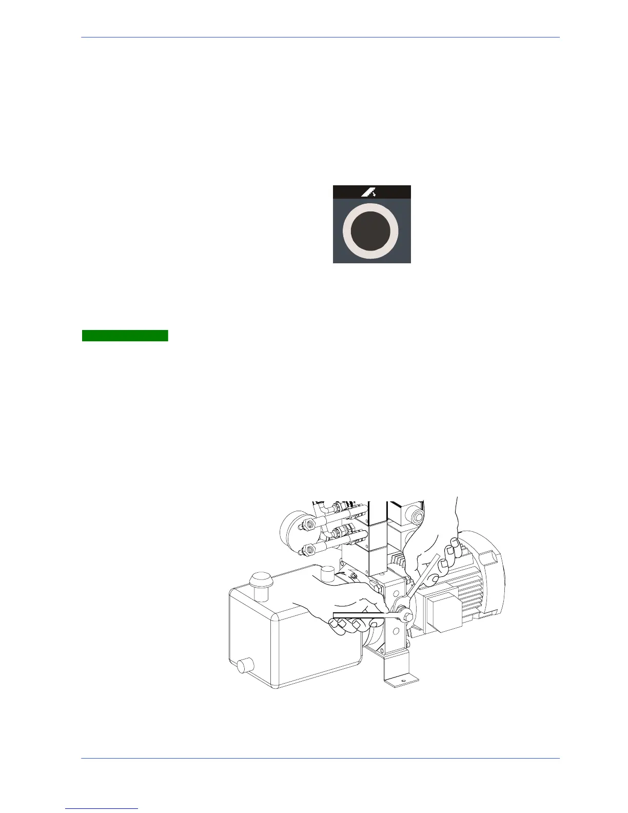
" Open the door of the machine base, remove the fastening screws and pull out
the power pack from inside the base.
" Slacken the hex nut on the relief valve, and using an Allen key, increase
(clockwise) or reduce (counter---clockwise) the pressure reading on the pres-
sure gauge.
" This done, tighten the lock nut and return the hydraulic power pack back in-
side the base.
Warning