MAX200 SETUP
3f-2 CommandTHC for X-Y Table Instruction Manual
11
See Figure 3f-1.
1. Remove access covers from the power supply, as required.
2. Locate the input/output panel on the back of the power supply.
3. Install the arc voltage wires:
Fabricate the wires as follows:
• Use 18AWG (0.9 mm
2
), single pair, unshielded wire, rated for 600V or greater.
• Wire length: As required, from the power supply to the plasma interface assembly.
• After installing the wires from the power supply to the plasma interface assembly, install appropriate
size fork or ring terminals on the wire ends.
Connect one of the wires to the WORK LEAD (+) connection of the input/output panel. Label this wire
positive (+).
Connect the other wire to the NEGATIVE LEAD (–) connection of the input/output panel. Label this wire
negative (–).
At the plasma interface assembly, connect the negative (–) wire to the J5-2 terminal labeled
ELECTRODE. Connect the positive (+) wire to the J5-3 terminal labeled WORK.
Electrode and work lead arc voltage wires
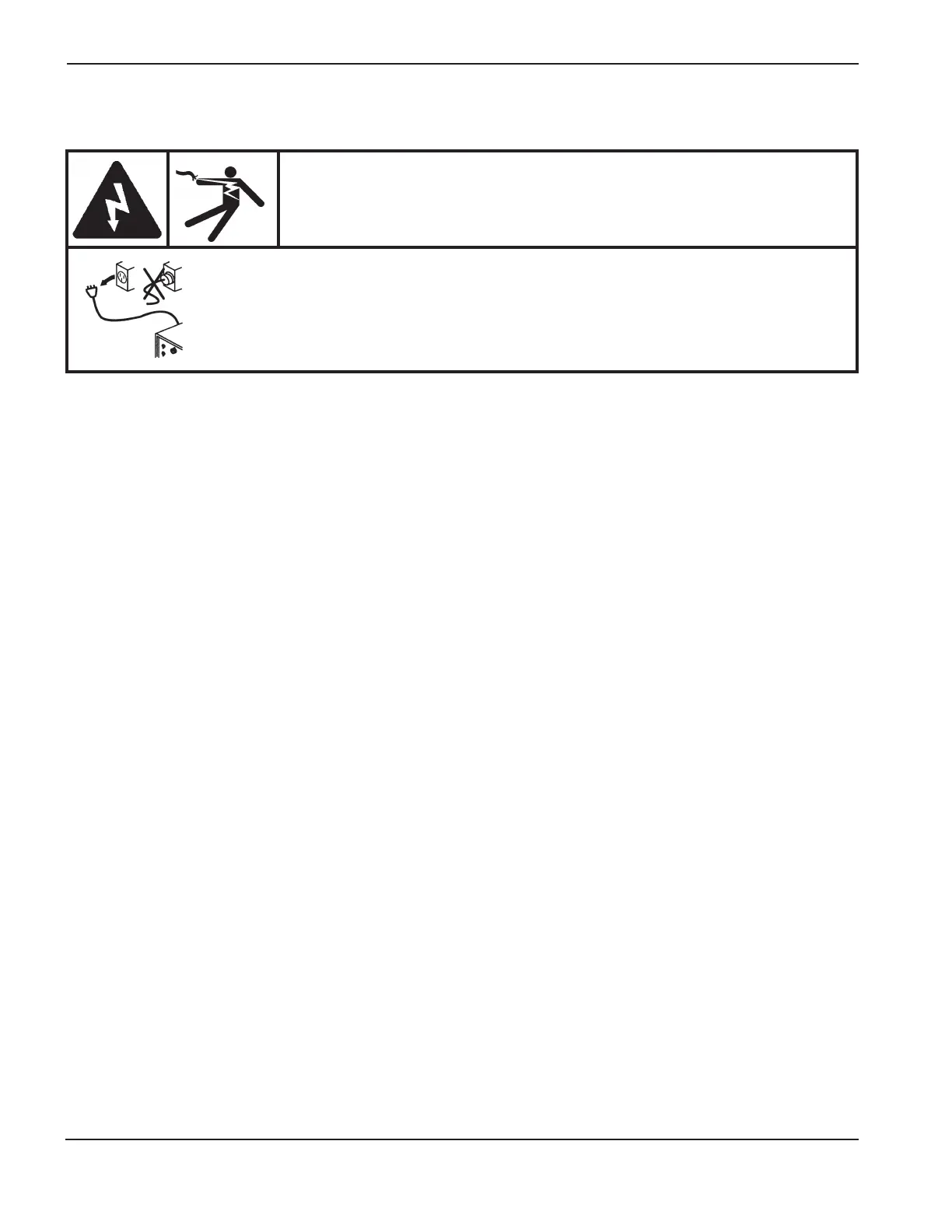
DANGER
ELECTRIC SHOCK CAN KILL
Turn off all electrical power before removing the power supply cover. Press the power
supply OFF (0) pushbutton switch and set the line disconnect switch to OFF. In the
U.S., use a “lock-out and tag-out” procedure until the service or maintenance is
complete. In other countries, follow appropriate local or national safety procedures.