TABLE OF CONTENTS
CommandTHC for X-Y Table Instruction Manual ix
11
Plasma interface cable............................................................................................................................................................................3-22
CNC interface cable ...............................................................................................................................................................................3-23
Pendant extension cable........................................................................................................................................................................3-25
Motor drive cable .....................................................................................................................................................................................3-26
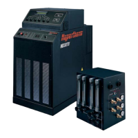
HD3070 system interconnections .......................................................................................................................................................3a-1
HT2000 system interconnections........................................................................................................................................................3b-1
HT2000LHF system interconnections................................................................................................................................................3c-1
HT4001 system interconnections........................................................................................................................................................3d-1
MAX100 System interconnections......................................................................................................................................................3e-1
MAX200 System interconnections.......................................................................................................................................................3f-1
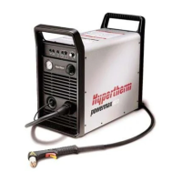
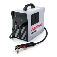
POWERMAX system interconnections..............................................................................................................................................3g-1
HT4400 system interconnections........................................................................................................................................................3h-1
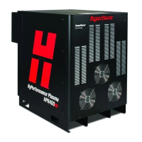
HPR system interconnections................................................................................................................................................................3i-1
HSD system interconnections................................................................................................................................................................3j-1
HD4070 system interconnections..................................................................................................................................See IM 803760
Section 4 OPERATION
Operating controls ....................................................................................................................................................................................4-2
THC control module........................................................................................................................................................................4-2
Operator pendant ............................................................................................................................................................................4-2
Pendant display screens................................................................................................................................................................4-4
Pendant programmable fields ......................................................................................................................................................4-6
Automatic operation screen ....................................................................................................................................................4-6
Manual operation screen ..........................................................................................................................................................4-8
Setup screen A ..........................................................................................................................................................................4-9
Determining pierce height factor..........................................................................................................................................................4-11
Typical pierce height factor ........................................................................................................................................................4-11
Pierce height factor for thicker materials ................................................................................................................................4-12
THC operating cycle time-lines ............................................................................................................................................................4-14
Automatic mode time-line............................................................................................................................................................4-15
Problems and solutions................................................................................................................................................................4-16
Manual mode time-line ................................................................................................................................................................4-18
THC selectable responses (DIP switch) ..............................................................................................................See section 3 Setup
Section 5 MAINTENANCE
Routine maintenance ................................................................................................................................................................................5-2
X-Y lifter sealing band removal and replacement ................................................................................................................................5-2
Troubleshooting ..........................................................................................................................................................................................5-6
Diagnostic screen B........................................................................................................................................................................5-6
Error messages ................................................................................................................................................................................5-6
AC power distribution ..................................................................................................................................................................5-10
Motor drive board status lights during normal power-up ....................................................................................................5-11
DC power distribution..................................................................................................................................................................5-12
Control board status lights during normal power-up ............................................................................................................5-14
Interface board status lights during normal power-up..........................................................................................................5-16
 Loading...
