MAINTENANCE
HPR130 Manual Gas Instruction Manual 5-11
5
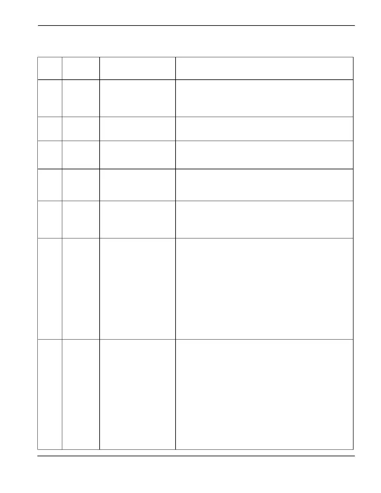
Error code troubleshooting (5 of 6)
Error
code
No.
Name Description Corrective action
1. Verify that the transformer temperature sensor for the
chopper has not been jumped out or the wires to the
temperature sensor are not shorted out in the harness.
2. If not, the main transformer is overheated and needs time to
cool to 150° C (302° F).
102
Output
current at
power-up
No current or over-current
detected during chopper
test at power-up.
1. Verify that proper electrical connections to chopper current
sensor (CS1) and to J3.200 at PCB3.
1. Verify that the electrical connections to current sensors CS1
And CS3 are correct and not damaged.
2. Replace PCB 3 if connections are correct and not damaged.
109
Coolant flow
at power-up
Coolant flow OK signal
is active during power-up
and before pump motor
is activated.
1. Either coolant flow sensor was bypassed or the flow switch is
faulty.
1. Verify that the coolant temperature sensor has not been
jumped out or the wires to the sensor are not shorted out in the
harness.
2. If not, the coolant temperature is over the set point and
needs time to cool to 70° C (158° F).
1. Verify that cable No. 5 (power supply to gas console control
cable) is not damaged and is properly connected to PCB3 and
the back of the gas console.
2. Verify that cable No. 6 (power supply to gas console power
cable) is not damaged and is properly connected inside the
power supply and to the back of the gas console.
3. Verify that D1 (+5 VDC) and D2 (+3.3 VDC) are illuminated
on PCB2 inside the gas console. These LEDs indicate power to
PCB2.
4. If power is present at PCB2 and PCB3 and both gas console
cables are good, then PCB2 or PCB3 has failed. Use the CAN
tester to verify which board needs to be replaced.
1. Verify that the part numbers of PCB2 and PCB3 are correct.
2. Verify That cable No. 5 (power supply to gas console control
cable) is not damaged and is properly connected to PCB3 and
the back of the gas console.
3. Verify that cable No. 6 (power supply to gas console power
cable) is not damaged and is properly connected inside the
power supply and to the back of the gas console.
4. Verify that D1 (+5 VDC) and D2 (+3.3 VDC) are illuminated
on PCB2 inside the gas console. These LEDs indicate power to
PCB2.
5. If power is present at PCB2 and PCB3 and both gas console
cables are good, then PCB2 or PCB3 has failed. Use the CAN
tester to verify which board needs to be replaced.
101
Magnetics
over temp at
power-up
Main transformer is
indicating an over temp at
power-up.
108
Transfer at
initialization
The system has detected
current on the work lead
during power-up
111
Coolant over
temp at
power-up
Coolant is indicating an
over temp at power-up.
116
Watchdog
interlock
An error occurred with the
CAN communication
system.
133
Unknown
gas console
type
The power supply control
board does not recognize
the gas console that is
installed or has not
received a CAN message.
 Loading...


