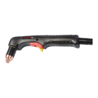
OPERATION
HySpeed HT2000LHF Instruction Manual 4-15
Shield Arc Approx.
Material
Plasma Gas Flow Rate %
Gas (CO
2
) Torch-to-work Initial Torch Voltage Motion
Thickness Preflow Cutflow Pressure Distance Piercing Height Setting Travel Speed Delay Time
(inches) (mm) (N
2
%) (N
2
%) (psi) (inches) (mm) (inches) (mm) (volts) (ipm) (mm/min.) (sec)
3/16 5 50 60 60/4 1/8 3 1/4 6 120 130 3300 0.5
1/4 6 (62.3 (75.0 (270 1/8 3 1/4 6 125 110 2800 1.0
3/8 10 (SCFH) SCFH) SCFH) 1/8 3 1/4 6 130 85 2160 1.5
1/2 12 1/8 3 1/4 6 130 55 1400 2.0
5/8 15 .157 4 .314 8 135 45 1140 2.0
3/4 20 3/16 5 3/8 10 145 25 635 2.5
7/8 22 1/4 6 1/2 12 150 20 510 3.0
1 25 1/4 6 1/2 12 160 15 380 3.0
1-1/4 32 1/4 6 165 10 250
1-1/2 38 1/4 6 175 5 130
Mild Steel
200 amps • N
2
Plasma / CO
2
Shield
This gas combination may be used when cut edge quality and surface nitriding are less important. Electrode life is
extended when using this combination.
Notes: Set plasma gas inlet pressure to 120 psi (8.3 bar)
Set shield gas inlet pressure to 90 psi (6.2 bar)
Production cutting above 1" (25 mm) not recommended
Above Water Only
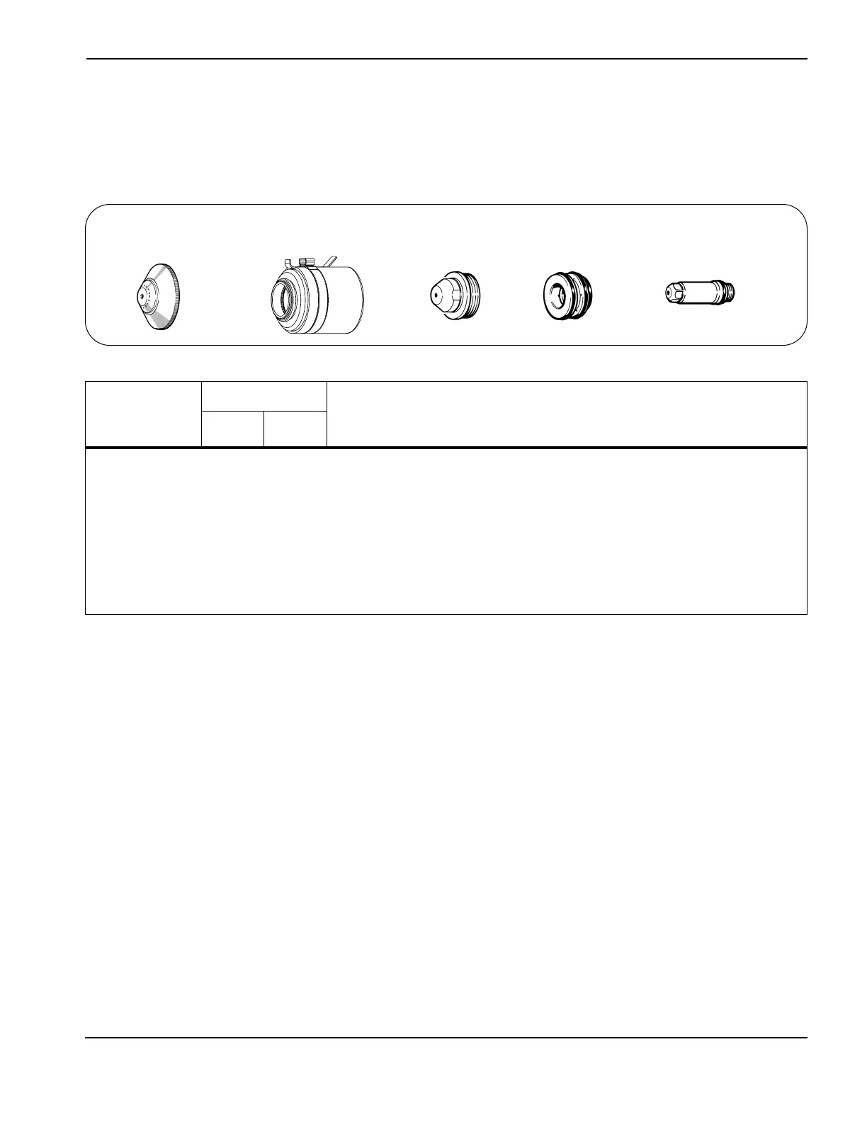
020424
Shield
120837
Retaining cap
020608
Nozzle
020607
Swirl ring
020415
Electrode
7
 Loading...