OPERATION
4-16 HySpeed HT2000LHF Instruction Manual
7
Shield Arc Approx.
Material
Plasma Gas Flow Rate %
Gas (Air) Torch-to-work Initial Torch Voltage Motion
Thickness Preflow Cutflow Pressure Distance Piercing Height Setting Travel Speed Delay Time
(inches) (mm) (Air %) (Air %) (psi) (inches) (mm) (inches) (mm) (volts) (ipm) (mm/min.) (sec)
Shield Arc Approx.
Material
Plasma Gas Flow Rate %
Gas (Air) Torch-to-work Initial Torch Voltage Motion
Thickness Preflow Cutflow Pressure Distance Piercing Height Setting Travel Speed Delay Time
(inches) (mm) (Air %) (Air %) (psi) (inches) (mm) (inches) (mm) (volts) (ipm) (mm/min.) (sec)
.075* 2 48 39 60 3/32 2.5 3/16 5 120 235 6050
1/8 3 (55.3 (44.9 (270 3/32 2.5 3/16 5 125 185 4700 0.5
3/16 5 SCFH) SCFH) SCFH) 1/8 3 1/4 6 125 175 4450 0.5
1/4 6 1/8 3 1/4 6 130 125 3175 0.5
3/8 10 1/8 3 1/4 6 135 50 1270 1.0
1/2 12 1/8 3 140 35 890
5/8 15 .157 4 145 25 635
3/4 20 3/16 5 150 20 510
Mild Steel
100* amps • Air Plasma / Air Shield
This gas combination gives good cut speed, low dross levels and is very economical. Some surface nitriding can
occur. While this process may be used on thicker materials, optimal recommended range is to 3/8" (10mm).
* Set arc current to 80 amps when cutting .075" (2 mm) thick mild steel
Notes: Set plasma gas inlet pressure to 90 psi (6.2 bar)
Set shield gas inlet pressure to 90 psi (6.2 bar)
Production cutting above 3/8" (10 mm) not recommended
Above Water
1/8 3 48 39 70 5/64 2 5/32 4 130 120 3050
3/16 5 (55.3 (44.9 (270 1/8 3 1/4 6 135 90 2300 0.5
1/4 6 SCFH) SCFH) SCFH) 1/8 3 1/4 6 140 70 1730 0.5
3/8 10 1/8 3 1/4 6 145 42 1050 0.5
1/2 12 1/8 145 28 700
3" Under Water
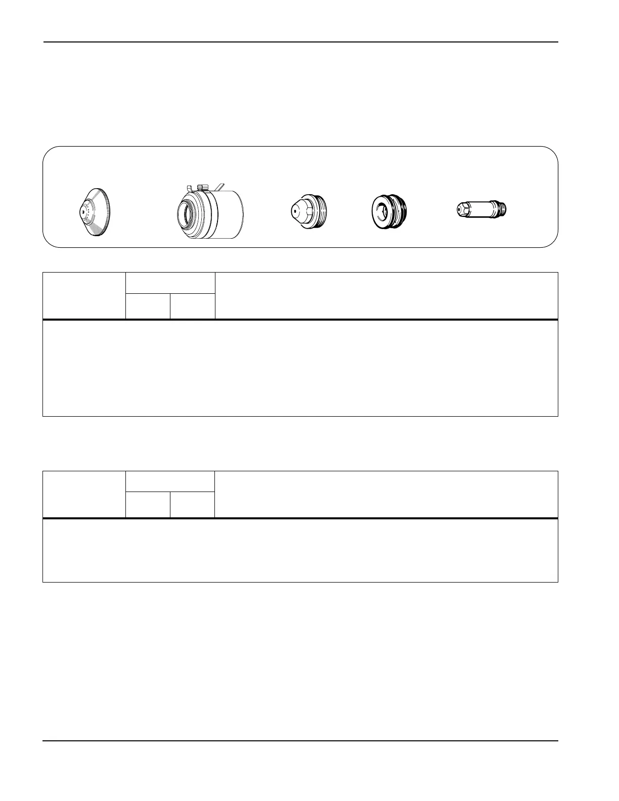
020448
Shield
120837
Retaining cap
020611
Nozzle
020607
Swirl ring
120547
Electrode
 Loading...