OPERATION
4-18 HySpeed HT2000LHF Instruction Manual
7
Shield Arc Approx.
Material
Plasma Gas Flow Rate %
Gas (O
2
) Torch-to-work Initial Torch Voltage Motion
Thickness Preflow Cutflow Pressure Distance Piercing Height Setting Travel Speed Delay Time
(inches) (mm) (O
2
%N
2
%) (O
2
%N
2
%) (psi) (inches) (mm) (inches) (mm) (volts) (ipm) (mm/min.) (sec)
.048 (18 GA.) 327 300 18 .060 1.50 .120 3.0 108 160 4060 0
.074 (14 GA.) 2 / 17 18 / 0 17 .060 1.50 .120 3.0 108 120 3050 0.3
.100 (12 GA.) l/min l/min l/min .070 1.75 .140 3.5 113 100 2540 0.3
.125 (10 GA.) .080 2.00 .160 4.0 118 60 1520 0.5
Mild Steel
50 amps • O
2
Plasma / O
2
Shield
Notes: Set oxygen plasma gas inlet pressure to 120 psi (8.3 bar)
Set nitrogen plasma gas inlet pressure to 120 psi (8.3 bar)
Set shield gas inlet pressure to 120 psi (8.3 bar)
The oxygen shield gas must be supplied from a regulator separate from the oxygen plasma gas regulator.
If using the Digital Remote (DR) or Programmable Remote (PR), set current to 60 amps.
If using a torch height control system capable of achieving the arc voltage setting on this chart, set accordingly.
If using a less sensitive torch height control system, round off the arc voltage numbers to the nearest achievable
setting.
Torch-to-work Distance tolerances are ± .010 inch (± .25 mm). When using a THC the tolerances are ± 1 volt.
Stay within travel speed ranges to produce dross-free cuts.
Due to the low gas flow rates associated with the 50 amp process, initial cut quality may be degraded while nitrogen is
being purged from the gas line when changing from preflow to cut flow (up to 2 seconds). To compensate, either
increase machine motion delay or increase the lead-in distance at the start of the cut.
Note that some height control systems may need to be locked out to prevent the torch from diving into the plate if the
machine motion delay option is used.
Above Water Only
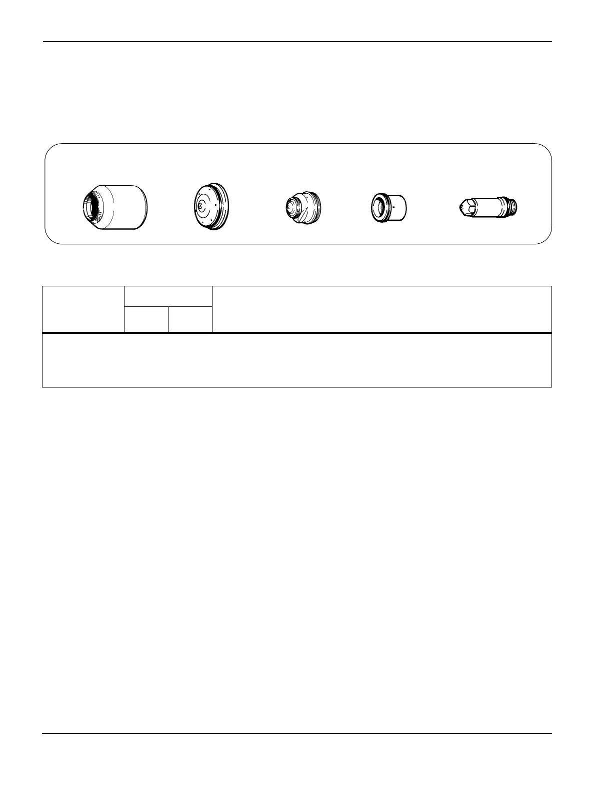
120185
Retaining cap
120186
Shield
120182
Nozzle
120179
Swirl ring
120178
Electrode
 Loading...