OPERATION
HySpeed HT2000LHF Instruction Manual 4-19
Shield Arc Approx.
Material
Plasma Gas Flow Rate %
Gas (Air) Torch-to-work Initial Torch Voltage Motion
Thickness Preflow Cutflow Pressure Distance Piercing Height Setting Travel Speed Delay Time
(inches) (mm) (Air %) (Air %) (psi) (inches) (mm) (inches) (mm) (volts) (ipm) (mm/min.) (sec)
Shield Arc Approx.
Material
Plasma Gas Flow Rate %
Gas (Air) Torch-to-work Initial Torch Voltage Motion
Thickness Preflow Cutflow Pressure Distance Piercing Height Setting Travel Speed Delay Time
(inches) (mm) (Air %) (Air %) (psi) (inches) (mm) (inches) (mm) (volts) (ipm) (mm/min.) (sec)
3/16 5 54 65 60 1/8 3 1/4 5 125 220 5600
1/4 6 (62.3 (75.0 (270 1/8 3 1/4 6 130 195 5000 0.5
3/8 10 SCFH) SCFH) SCFH) 1/8 3 1/4 6 130 145 3700 1.0
1/2 12 1/8 3 1/4 6 135 105 2700 2.0
5/8 15 .157 4 .314 8 140 75 1900 2.0
3/4 20 3/16 5 3/8 10 140 55 1400 2.5
7/8 22 1/4 6 1/2 12 145 40 1000 3.0
1 25 1/4 6 150 30 760
1-1/4 32 ` 1/4 6 160 15 380
1-1/2 38 1/4 6 170 10 250
Stainless Steel
200 amps • Air Plasma / Air Shield
This gas combination gives good cut speed, low dross and is very economical. Some surface nitriding and surface
oxidation of alloying elements can occur.
Notes: Set air plasma gas inlet pressure to 90 psi (6.2 bar)
Set air shield gas inlet pressure to 90 psi (6.2 bar)
Production cutting above 7/8" (22 mm) not recommended
Above Water
3/16 5 54 65 70 1/8 3 1/4 6 125 210 5320
1/4 6 (62.3 (75.0 (280 1/8 3 1/4 6 130 180 4500 0.5
3/8 10 SCFH) SCFH) SCFH) 1/8 3 1/4 6 135 125 3150 1.0
1/2 12 1/8 3 1/4 6 140 90 2300 2.0
5/8 15 .157 4 .314 8 145 60 1520 2.0
3/4 20 3/16 5 3/8 10 145 45 1150 2.5
7/8 22 1/4 6 1/2 12 150 30 750 3.0
1 25 1/4 6 155 22 570
3" Under Water
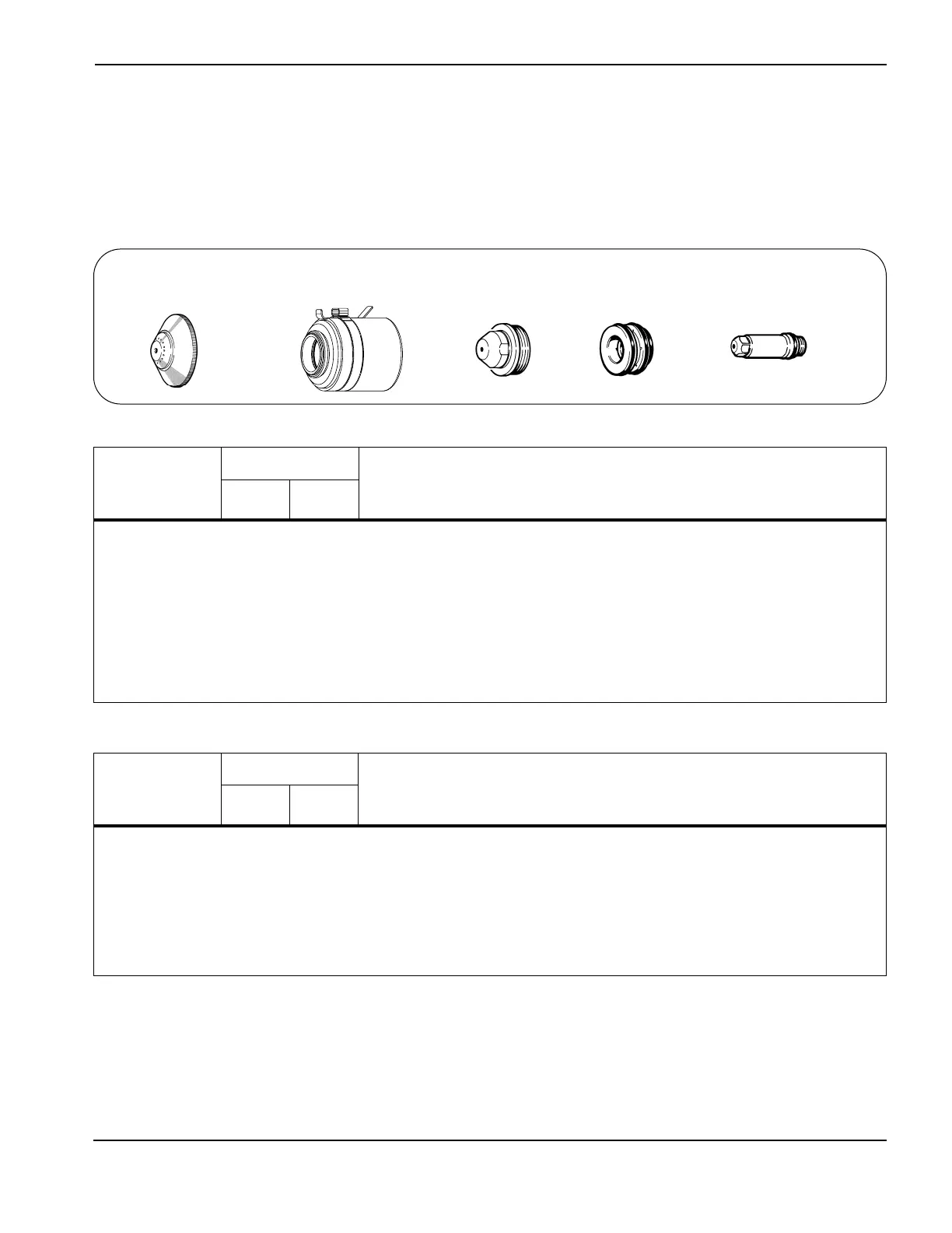
020424
Shield
120837
Retaining cap
020608
Nozzle
020679
Swirl ring
120667
Electrode
7
 Loading...