OPERATION
4-22 HySpeed HT2000LHF Instruction Manual
7
Shield Arc Approx.
Material
Plasma Gas Flow Rate %
Gas (Air) Torch-to-work Initial Torch Voltage Motion
Thickness Preflow Cutflow Pressure Distance Piercing Height Setting Travel Speed Delay Time
(inches) (mm) (Air %) (Air %) (psi) (inches) (mm) (inches) (mm) (volts) (ipm) (mm/min.) (sec)
Shield Arc Approx.
Material
Plasma Gas Flow Rate %
Gas (Air) Torch-to-work Initial Torch Voltage Motion
Thickness Preflow Cutflow Pressure Distance Piercing Height Setting Travel Speed Delay Time
(inches) (mm) (Air %) (Air %) (psi) (inches) (mm) (inches) (mm) (volts) (ipm) (mm/min.) (sec)
1/8 3 48 39 60 3/32 2.5 3/16 5 125 140 3560
3/16 5 (53.3 (44.9 (270 1/8 3 1/4 6 130 110 2800 0.5
1/4 6 SCFH) SCFH) SCFH) 1/8 3 1/4 6 130 80 2030 0.5
3/8 10 1/8 3 1/4 6 135 55 1400 0.5
1/2 12 1/8 3 140 35 890
5/8 15 .157 4 145 25 635
3/4 20 3/16 5 150 20 510
Stainless Steel
100 amps • Air Plasma / Air Shield
This gas combination gives good cut speed, low dross and is very economical. Some surface nitriding and surface
oxidation of alloying elements can occur.
Notes: Set air plasma gas inlet pressure to 90 psi (6.2 bar)
Set air shield gas inlet pressure to 90 psi (6.2 bar)
Production cutting above 3/8" (10 mm) not recommended
Above Water
1/8 3 48 39 60 5/64 2 5/32 4 125 135 3400
3/16 5 (53.3 (44.9 (270 1/8 3 1/4 6 130 100 2520 0.5
1/4 6 SCFH) SCFH) SCFH) 1/8 3 1/4 6 135 65 1720 0.5
3/8 10 1/8 3 1/4 6 140 45 1120 0.5
1/2 12 1/8 3 145 25 670
3" Under Water
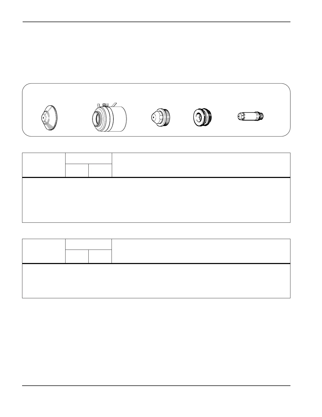
020448
Shield
120837
Retaining cap
020611
Nozzle
020607
Swirl ring
120547
Electrode
 Loading...