OPERATION
HySpeed HT2000LHF Instruction Manual 4-21
Shield Arc Approx.
Material
Plasma Gas Flow Rate %
Gas (CO
2
) Torch-to-work Initial Torch Voltage Motion
Thickness Preflow Cutflow Pressure Distance Piercing Height Setting Travel Speed Delay Time
(inches) (mm) (N
2
%) (N
2
%) (psi) (inches) (mm) (inches) (mm) (volts) (ipm) (mm/min.) (sec)
Shield Arc Approx.
Material
Plasma Gas Flow Rate %
Gas (CO
2
) Torch-to-work Initial Torch Voltage Motion
Thickness Preflow Cutflow Pressure Distance Piercing Height Setting Travel Speed Delay Time
(inches) (mm) (N
2
%) (N
2
%) (psi) (inches) (mm) (inches) (mm) (volts) (ipm) (mm/min.) (sec)
3/16 5 50 60 60 1/8 3 1/4 6 125 190 4800 0.5
1/4 6 (66.4 (79.6 (210 1/8 3 1/4 6 130 170 4300 1.0
3/8 10 SCFH) SCFH) SCFH) 1/8 3 1/4 6 130 125 3200 1.5
1/2 12 1/8 3 1/4 6 135 95 2400 2.0
5/8 15 .157 4 .314 8 140 70 1800 2.0
3/4 20 3/16 5 3/8 10 140 50 1250 2.5
7/8 22 1/4 6 1/2 12 145 40 1000 3.0
1 25 1/4 6 150 30 760
1-1/4 32 ` 1/4 6 160 15 380
1-1/2 38 1/4 6 170 10 250
Stainless Steel
200 amps • N
2
Plasma / CO
2
Shield
This gas combination is used when surface nitriding and surface oxidation of alloying elements is less important.
Electrode life is extended when using this gas combination.
Notes: Set nitrogen plasma gas inlet pressure to 120 psi (8.3 bar)
Set carbon dioxide shield gas inlet pressure to 90 psi (6.2 bar)
Production cutting above 7/8" (22 mm) not recommended
Above Water
3/16 5 50 60 60 1/8 3 1/4 6 125 180 4550 0.5
1/4 6 (66.4 (79.6 (210 1/8 3 1/4 6 130 150 3850 1.0
3/8 10 SCFH) SCFH) SCFH) 1/8 3 1/4 6 135 110 2700 1.5
1/2 12 1/8 3 1/4 6 140 75 1920 2.0
5/8 15 .157 4 .314 8 145 50 1350 2.0
3/4 20 3/16 5 3/8 10 145 38 950 2.5
7/8 22 1/4 6 1/2 12 150 28 700 3.0
3" Under Water
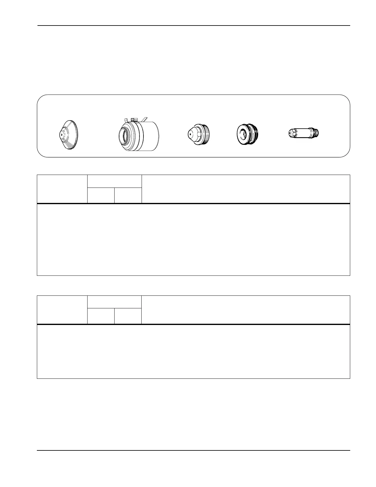
020424
Shield
120837
Retaining cap
020608
Nozzle
020607
Swirl ring
020415
Electrode
7
 Loading...