3-7
S
ETUP
Operator Manual
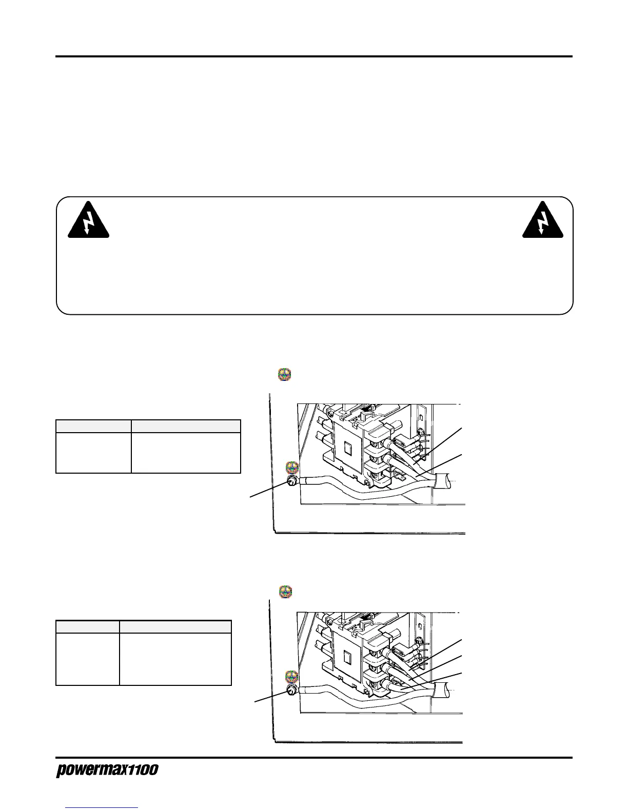
Conductor Color
L1 (U) Brown or Black
L2 (V) Blue or White
L3 (W) Black or Red
Ground Green/Yellow or Green
Three-Phase
Remove the rear panel (Fig. 3-2) and connect the power cable to the contactor as shown in Fig. 3-10.
Connect the ground wire to the stud marked .
Figure 3-10
Three-Phase Power
Blue
Black
Green/
Yellow
SINGLE-PHASE AND THREE-PHASE POWER CONFIGURATIONS
All Powermax1100 power supplies except the 230/400V CE and 600V power supplies can operate from
either a single-phase or three-phase input. The 230/400V CE and 600V power supplies operate only
from a three-phase input.
Power cords must meet the specifications described earlier in this section. Follow applicable local or
national wire color conventions. See also EMC Compatibility and
Mains Supply
on page i for further
CE compliance recommendations.
Single-Phase
Remove the rear panel (Fig. 3-2) and connect the power cable to contactor as shown in Fig. 3-9.
Connect the ground wire to the stud marked .
Black
White
Green
Figure 3-9
Single-Phase Power
Brown
Conductor Color
Line (U) Black or Brown
Neutral/Line (V) White or Blue
Ground Green or Green/Yellow
WARNING
SHOCK HAZARD: Always turn off the power, unplug the cord and wait 5 minutes before
removing any power supply cover. If the power supply is directly connected to a line
disconnect switch, place switch in the OFF position. In the U.S., use a "lock-out / tag-out"
procedure until the service or maintenance work is complete. In other countries, follow
appropriate local or national safety procedures.