EasyManuals Logo

Hypertherm Powermax45 XP Field Service Bulletin

Hypertherm Powermax45 XP
30 pages
To Next Page IconTo Next Page
To Previous Page IconTo Previous Page
Page #29 background imageLoading...
Page #29 background image
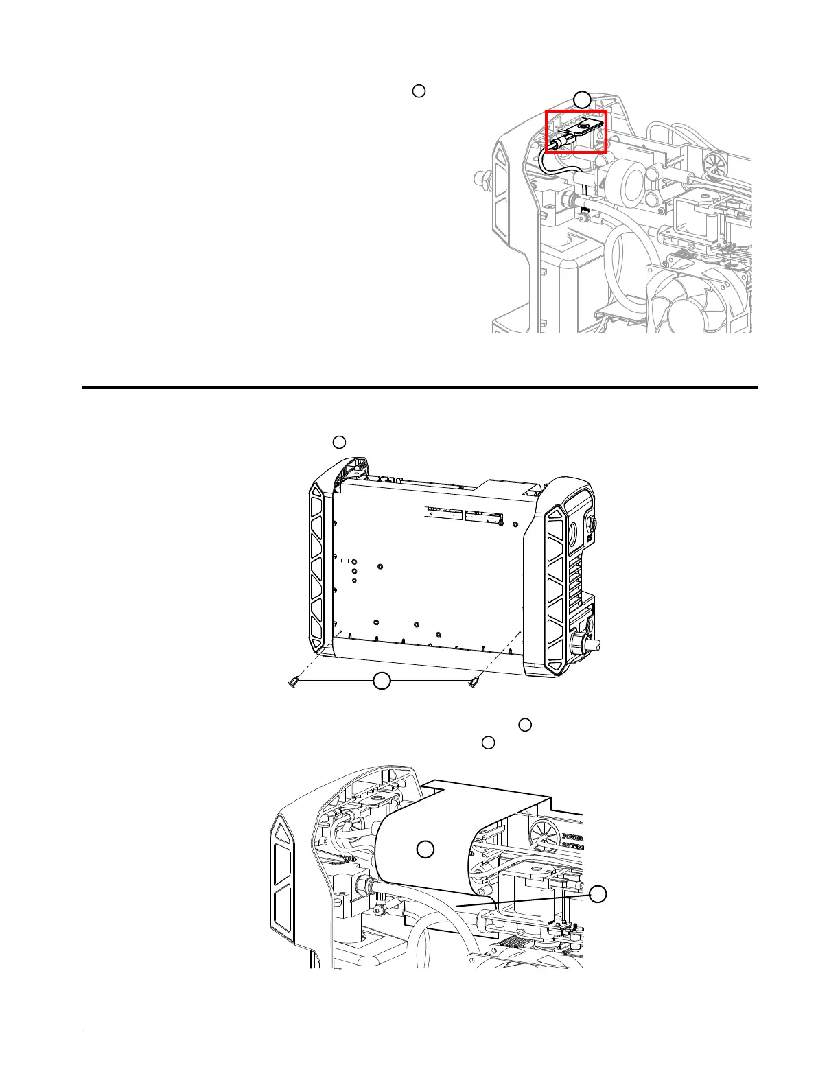
Câble d’interface de machine avec diviseur de tension
Powermax45 XP Bulletin de service sur le terrain 809940 29
6. S’assurer que la borne de mise à la terre est
branchée au fil de terre.
7. Positionner la borne de mise à la terre de façon
à ce qu’elle soit alignée avec la vis de la poignée.
Installation des composants extérieurs
1. Fixer la barrière de composants à la carte à circuits imprimés de la source de courant à l’aide
des 2 goupilles en plastique .
2. Placer la partie plus longue de la barrière de composants par-dessus les branchements
du cordon d’alimentation et derrière le tuyau de gaz .
7
1
1
2
3
2
3

Other manuals for Hypertherm Powermax45 XP

Questions and Answers:

Question and Answer IconNeed help?

Do you have a question about the Hypertherm Powermax45 XP and is the answer not in the manual?

Hypertherm Powermax45 XP Specifications

General IconGeneral
Output Current10-45 A
Gas SupplyClean, dry, oil-free air or nitrogen
Torch StyleHandheld or mechanized
Input Voltage50/60 Hz
Cutting Thickness12 mm (1/2")
Cutting Capacity16 mm (5/8 in)
Recommended Gas Inlet Flow Rate/Pressure6.2 bar

Related product manuals