Machine Interface Receptacle with Voltage Divider Board
8 809940 Field Service Bulletin Powermax45 XP
Install the cable holders
The cable holders help prevent electrical interference by keeping the 4-pin connector cable
away from other electrical components. Make sure that you install the cable holders
correctly.
If the plasma power supply already has cable holders installed, continue to Install the machine
interface receptacle with voltage divider PCB on page 9.
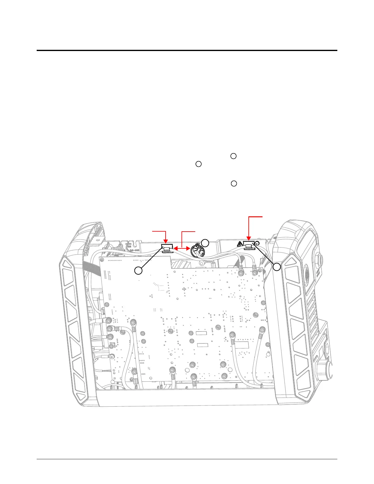
1. Turn the plasma power supply so that the power PCB is facing you.
2. Bond the cable holders to the middle panel with the openings of the cable holders pointing up.
The 4-pin connector cable is shown for reference.
a. Remove the adhesive cover on 1 of the cable holders and bond the cable holder 25 mm
(1 inch) to the left of the middle grommet and 2 mm (1/16 inch) below the edge of the
middle panel.
b. Remove the adhesive cover on the other cable holder and bond the cable holder
between the warning label and the middle panel screw, and 2 mm (1/16 inch) below the
edge of the middle panel.
25 mm (1 inch)
2mm (1/16 inch)
2mm (1/16 inch)
1
2
3