Hytera DMR System Planner
25
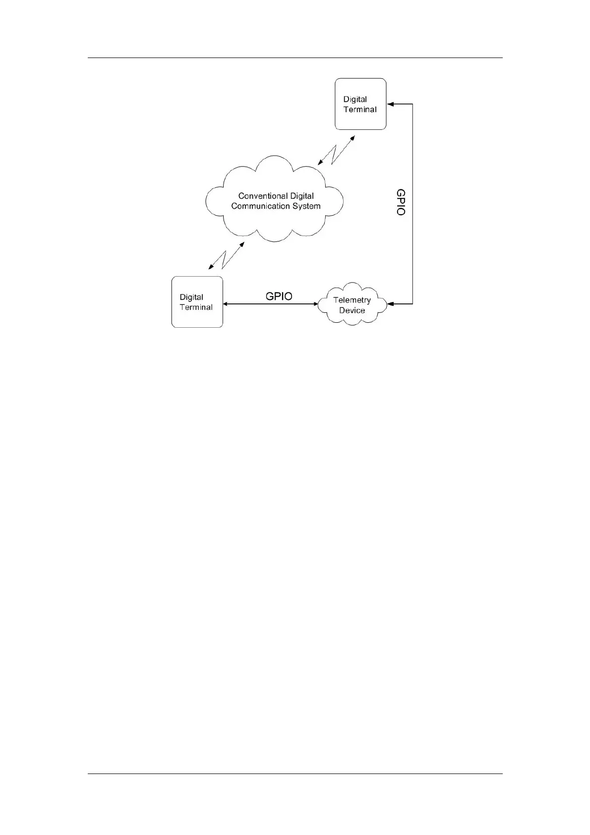
Figure 2.4.4-1: Telemetry Principle
The connection between the radio and the device is fulfilled by the third party who
will determine the connection form.
The portable radio supports one telemetry VIO (GPIO Pin1). The mobile radio
supports 6 telemetry VIOs. GPIO Pin3, Pin12, Pin 16, Pin20, Pin22 and Pin23 can
be set to the telemetry VIO.
For mobile radio:
High TTL: 3.6–5V; Low TTL: 0–2.4V
GPIO Pin input: 0–1.2V (low); 2.0–5V (high).
GPIO Pin output: 0–0.8V (low); 2.4–5V (high).
For portable radio:
GPIO Pin input: 0–0.3V (low); 0.7–3.3V (high).
GPIO Pin output: 0–0.22V (low); 0.8–3.3V (high).
GPIO Interface
GPIO Interface of Portable Radio
The portable radio supports one telemetry VIO, which is associated with GPIO Pin11.
See the following figure.

 Loading...