TDD RX Circuit
The TDD RF signal from the antenna goes to the ANT port of the PA (U1203), the TRX port, and then the
DUP for filtering. The filtered LTE signal goes to the PA (U1401), the switch for channel switching, and then
to the main receiving interface of the Transceiver (U1600).
The TDD main RX circuit consists of LTE B38.
5.1.2.4 Diversity RX Circuit
FDD RX Circuit
The FDD RF signal received by the antenna goes to the ANT port of the Switch (U1300), the RF port, and
then the filter. The filtered signal goes to the corresponding switch for channel switching and then the main
receiving port of the Transceiver (U1600). The filtered B2/B3/B4/B5/B7/B12/B13/B17/B26/B28 frequency
signal directly goes to the main receiving port of the Transceiver (U1600).
The FDD diversity RX circuit consists of LTE B2/B3/B4/B5/B7/B12/B13/B17/B26/B28.
TDD RX Circuit
The TDD RF signal received by the antenna goes to the ANT port of the Switch (U1300), the RF port, and
then the filter. The filtered signal goes to the main receiving interface of the Transceiver (U1600).
The TDD diversity RX circuit consists of LTE B38.
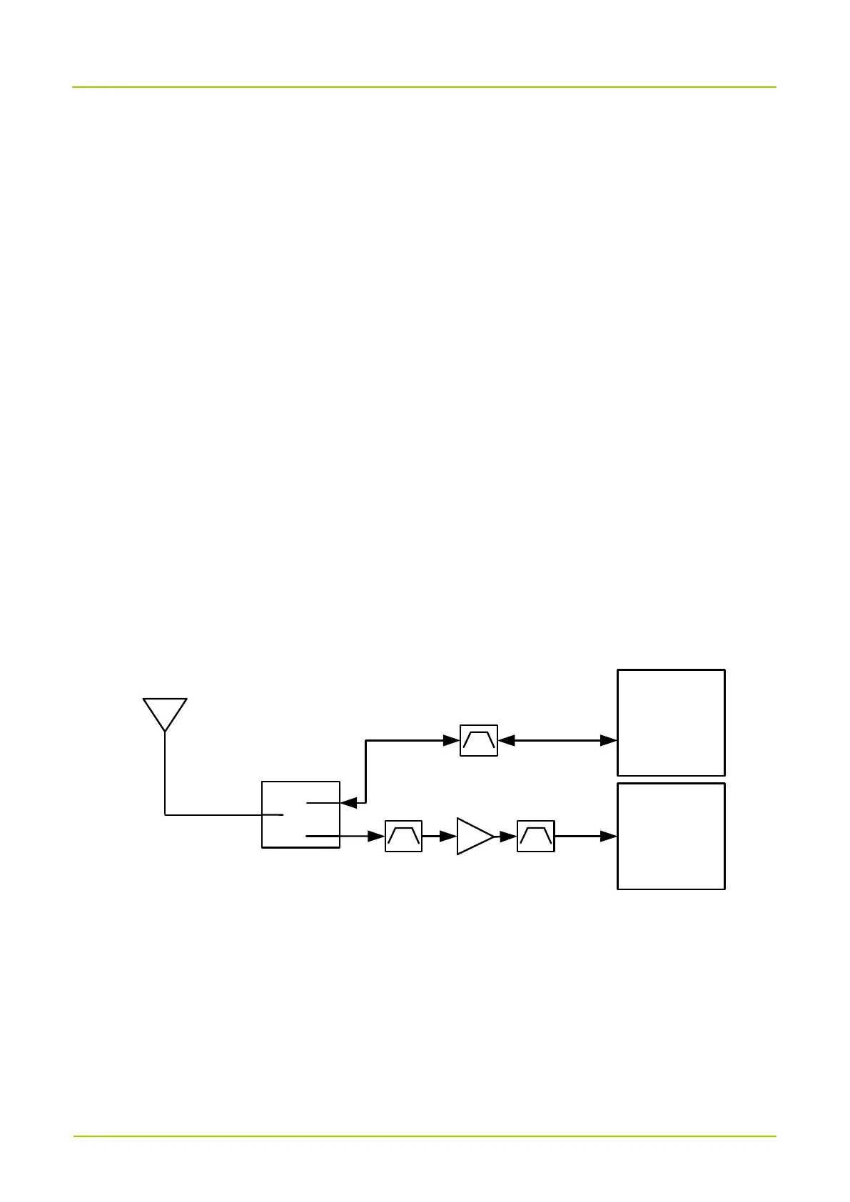
5.1.2.5 GNSS/WLAN/BT Circuit
ANT_GNSS/WLAN/BT
WLAN/BT
SW (FL1701)
ANT
LNA
RF
Transceiver
GNSS_IN
Wireless
Connectivity
IC
WL
_BT_RFIO
The GNSS signal goes to the Switch (FL1701) through the GNSS/WLAN/BT three-in-one antenna before
being shunted to the pre-filter for LNA amplification. The amplified signal passes through the post-filter to
the RF Transceiver for demodulation.
The WLAN/BT signal goes to the Switch (FL1701) through the GNSS/WLAN/BT three-in-one antenna, and
then passes through the filter to the WLAN module for demodulation. At the same time, the WLAN/BT
signal can be modulated in the WLAN module, and then passes through the filter and the Switch (FL1701)
to the GNSS/WLAN/BT three-in-one antenna for transmission.