EasyManua.ls Logo

Hytera PNC550 - Circuit Description; Baseband Section

Hytera PNC550
99 pages
Print Icon
To Next Page IconTo Next Page
To Previous Page IconTo Previous Page
Loading...
Circuit Description
B9
14
5. Circuit Description
5.1.1 Baseband Section
5.1.1.1 Control Module
Power Supply Module
User interfaces
+
LC network
-
LC network
Display
L-CR-C
network
Backlight
Flash/torc h
Haptics
ERM/
LRA
Input power
management
Charger
Fuel guage
Pmux
USB
connector
LC network
Input power
management
Output power
management
SMPS circuits
LDO circuits
LC network
Load caps
PMI
PMU
External
regulators
RFFE
RF
transceivers
Modem IC,
peripherals
Audio
Wireless
connectivity
VPH_PWR
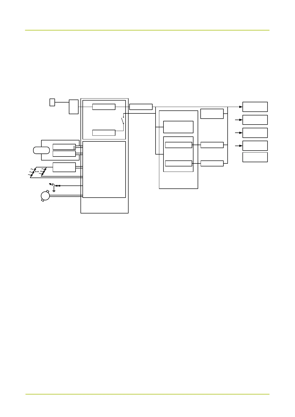
The power supply employs a 3.7 V battery. The power supply management IC consists of PMI, PMU, and
QFE.
The PMI is controlled by the CPU and is responsible for the power supply switch control and LCD
power supply.
The PMU is controlled by the CPU and integrates 7 DC/DCs and 23 LDOs to provide power for the
baseband section.
The QFE provides power to the RF section.