3. SCON-CA/CFA
96
(1) PLC address configuration (* “n” indicates the first address of each axis.)
Parameter
No.84
PCON-CA/CFA side
DI (Port No.)
PLC side output
address (bytes)
PCON-CA/CFA side
DO (Port No.)
PLC side input
address (bytes)
0 0 to 15 n+0, n+1 0 to 15 n+0, n+1
(Note) Be careful of using duplicated node addresses.
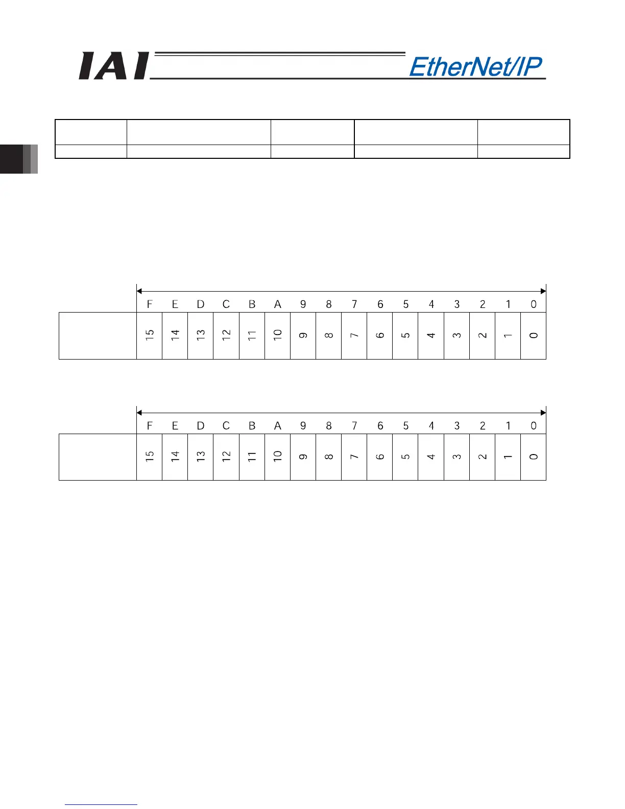
(2) I/O signal allocation for each axis
The I/O signals of each axis consist of one input word (1 word = 2 bytes) and one output word in the I/O
areas.
x This is controlled by ON/OFF bit signals from the PLC.
PCL output
Address (* “n” indicates the first output address of each axis.)
PCL input
Address (* “n” indicates the first input address of each axis.)
Controller
input port
number
1 word = 2 bytes =16 bit
n+0 n+1
Controller
output port
number
1 word = 2 bytes =16 bit
n+0 n+1

 Loading...


