4. SCON-CA
170
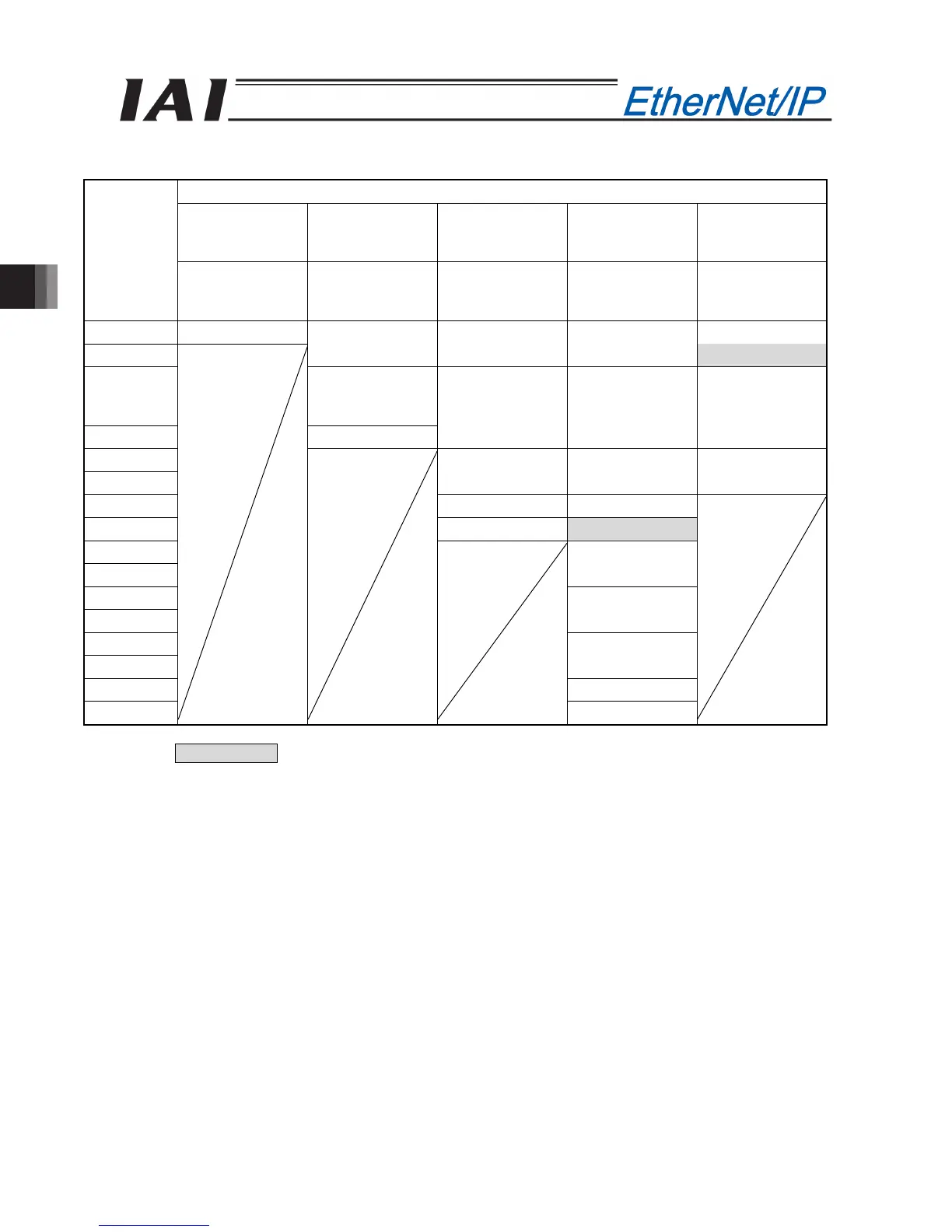
x SCON-CA output o PLC input (* “n” indicates the byte address of each axis.)
DO on the SCON-CA side and output data register
Remote I/O
mode
Position/
Simplified direct
value mode
Half direct value
mode
Full direct value
mode
Remote I/O
mode 2
PLC output
area (bytes)
Number of
occupied bytes:
2
Number of
occupied bytes:
8
Number of
occupied bytes:
16
Number of
occupied bytes:
32
Number of
occupied bytes:
12
n+0, n+1 Port No.0 to 15 Port No.0 to 15
n+2, n+3
Current position Current position Current position
Occupied area
n+4, n+5
Completed
position No.
(simple alarm ID)
n+6, n+7 Status signal
Command
current
Command
current
Current position
n+8, n+9
n+10, n+11
Current speed Current speed
Command
current
n+12, n+13 Alarm code Alarm code
n+14, n+15 Status signal Occupied area
n+16, n+17
n+18, n+19
Force feedback
data
n+20, n+21
n+22, n+23
Total moving
count
n+24, n+25
n+26, n+27
Total moving
distance
n+28, n+29 Status signal 1
n+30, n+31 Status signal 2
(Note) The Occupied area shows the area to be occupied with the operation mode setting.
Therefore, this area cannot be used for any other purpose. Also, exercise caution to avoid node address
duplication.

 Loading...


