58
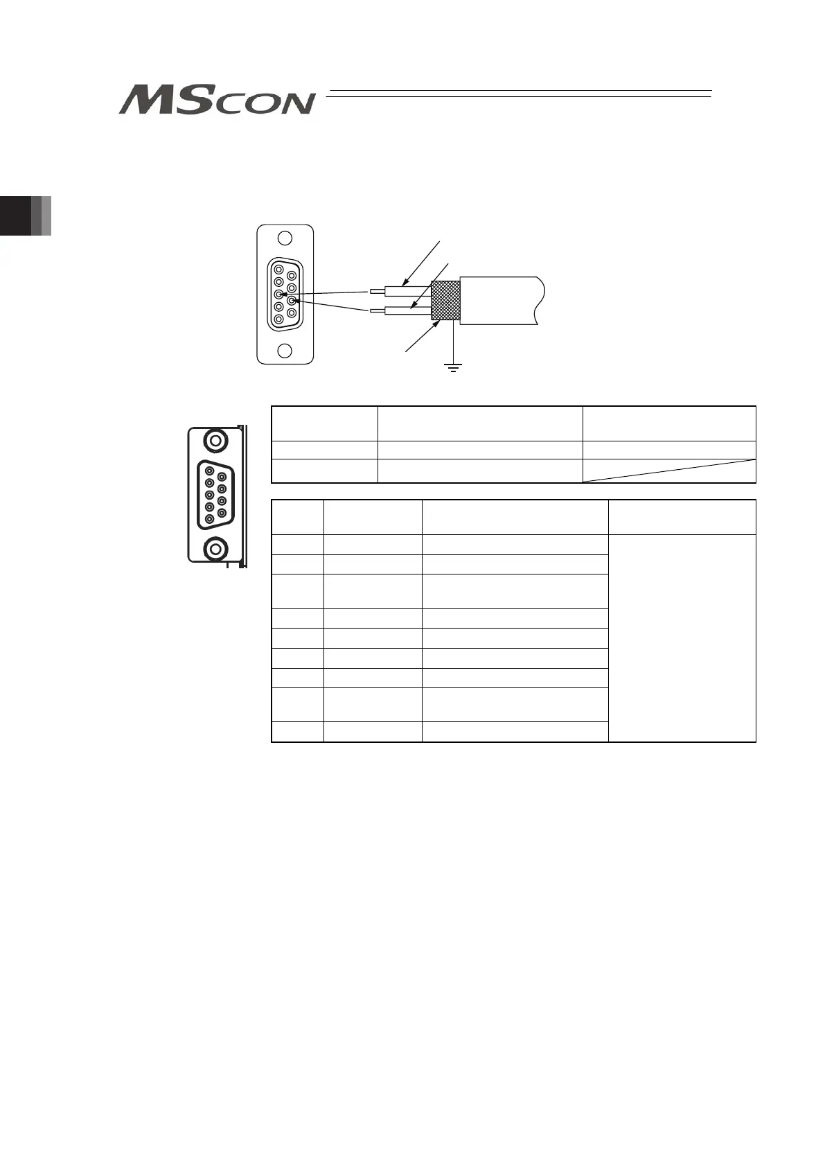
3) PROFIBUS-DP Type
5 1
9 6
Cable
Shield
Red B line (Positive side)
Use the type A cable for PROFIBUS-DP (EN5017).
Green A line (Negative side)
PROFIBUS-DP
Connector
Model Remarks
Cable Side D-sub 9-pin connector (Male) Please prepare separately
Controller Side D-sub 9-pin connector (Female)
Pin
No.
Signal Name Contents Applicable Cable
1 NC Unconnected
2 NC Unconnected
3 B-Line
Communications Line B
(RS485)
4 RTS Request for Sending
5 GND Signal GND (Insulated)
6 +5V +5V Output (Insulated)
7 NC Unconnected
8 A-Line
Communications Line A
(RS485)
9 NC Unconnected
PROFIBUS-DP
Dedicated Cable
(Note): Connect a terminal resistor (220Ω) between A-Line and B-Line to
the end of the network. [Refer to 2.2 [8] Field network Circuit (For
Field network Type)]
1
5
6
9
Front view of
connector on
controller side