3. SCON-CA
145
(2) I/O Signal Allocation for each Axis
The I/O signals of each axis consist of one input word (8 words = 16 bytes) and one output word in the I/O
areas.
z The control signals and status signals are ON/OFF signals in units of bit.
z The target position and current position are expressed using 2-word (32 bits) binary data. The figures
from –999999 to +999999 (Unit: 0.01mm) can be set in PLC. However, set the position data within the
soft stroke range (0 to effective stroke length) for the actuator concerned.
z Set the positioning band. The positioning band is expressed using 2-word (32 bits) binary data. The
figures from 1 to +999999 (Unit: 0.01mm) can be set in PLC.
z The specified speed is expressed using 1-word (16 bits) binary data. The figures from 0 to +65535 (Unit:
1.0mm/sec) can be set in PLC. Set the value that does not exceed the max. speed value
for the actuator
concerned.
z The Acceleration/Deceleration is expressed using 1-word (16 bits) binary data. The figures from 1 to 300
(Unit: 0.01G) can be set in PLC. However, set the value that does not exceed the max.
acceleration/deceleration value for the actuator in question.
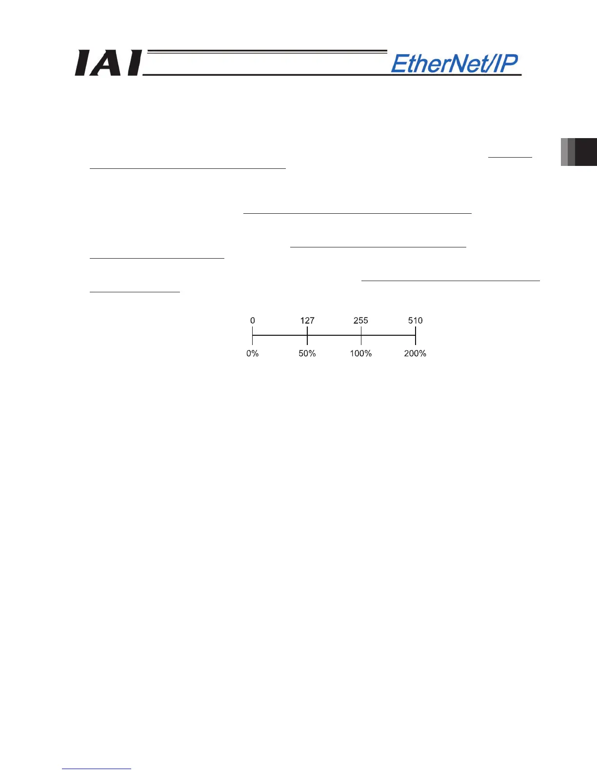
z The pressing current-limiting value is expressed using 1-word (16 bits) binary data. The figures from 0
(0%) to 510 (200%) can be set in PLC. However, set the value within the settable range for the pressing
current-limiting value (Refer to the Catalog or Operation Manual for the actuator) for the actuator
concerned.
Set Value
Pressing current-limiting value
z The command current is expressed using 2-word (32 bits) binary data (Unit: 1mA).
z The current speed is expressed using 2-word (32 bits) binary data (Unit: 0.01mm/sec).
z The alarm code is expressed using 1-word (16 bits) binary data.