Fieldbus Communication
13
RCP6
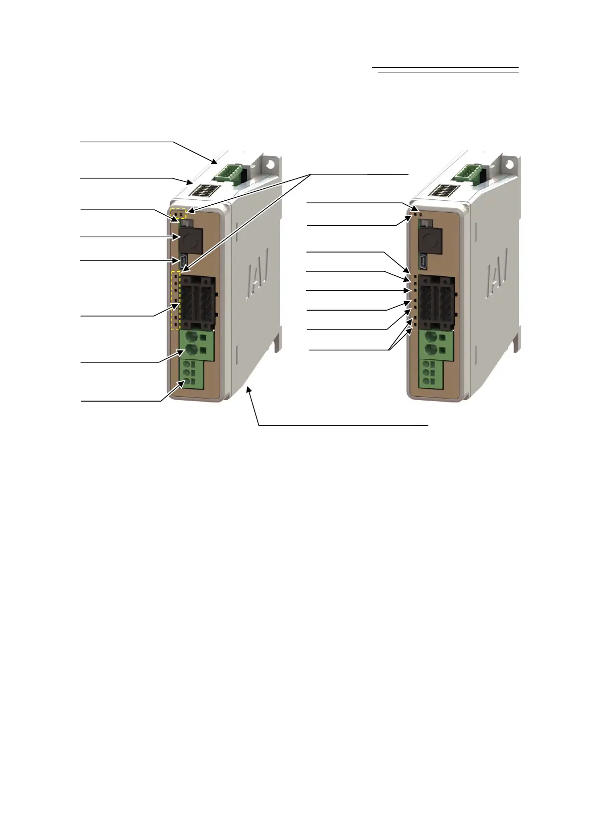
2. RCP6S Gateway Unit
1) Power Supply Connector
It is a connector for the 24V DC gateway control power supply and frame grounding (FG).
2) Motor Power Supply Connector
It is a connector for the 24V DC motor power supply to the gateway.
3) Drive Cutoff Connector
It is a connector to connect the external drive cutoff relay to 24V DC input from the motor power
supply connector.
4) USB Connector
It is a connector to connect such as a PC. Mini USB Connector is adopted.
5) SIO Connector
It is a connector to connect such as a teaching pendant or PC.
6) Operation Mode Setting Switch
This is a switch to change the operation mode between Automatic Operation (AUTO) and Manual
Operation (MANU).
7) System I/O Connector
It is a connector for the brake release input in case of connecting the actuator directly to the
emergency stop input, external AUTO/MANU switchover input or the gateway unit.
8) Fieldbus Connector
It is a connector for the fieldbus.
6) Operation Mode
Setting Switch
5) SIO Connector
4) USB Connector
2) Motor Power
Su
l
Connector
1) Power Supply
Connector
3) Drive Cutoff
Connector
) System I/O
Connector
8
Fieldbus Connecto
LED1: SYS
LED2: AUTO
LED3:
EMG
LED4: T. ERR
LED5: C. ERR
LED6: STATUS-0
LED7: STATUS-1
Not to be used
9) Status Display LED
[Bottom Surface]
10) to 17) Axis Control Connector
Axis Power Supply Connector
 Loading...
