upper controller is controller A; the lower controller is controller B. All connections to
the hosts and the drives in the storage configuration are through the controllers.
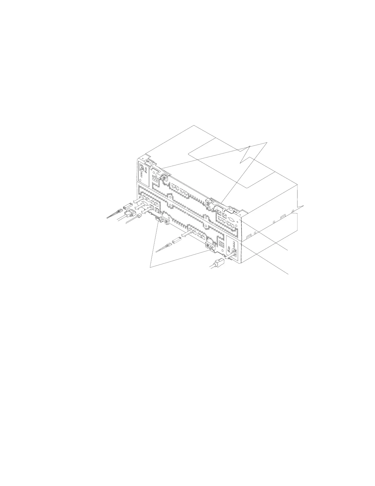
Figure 3 shows the controllers in the DS4800.
Note: Although both RAID controller units (A and B) in the DS4800 are identical,
they are seated in the DS4800 chassis in opposite orientations. As shown in
Figure 3, the controller units must be inserted in the DS4800 so that the
latches of each controller are on the exterior of the DS4800 chassis. The
latches on controller A line up with the top side of the DS4800 chassis; the
latches on controller B line up with the bottom side of the DS4800 chassis.
Information about the condition of the controllers is conveyed by indicator LEDs on
the back of each controller. (“RAID controller LEDs” on page 113 identifies the
indicator LEDs on the RAID controller and explains the conditions that each LED
indicates.)
Controller cable connections
Each controller provides the following connections:
v Two dual-ported fibre channel drive channels
v Four single-ported host channels
v Two RJ-45 Ethernet ports
v One RS-232 serial port
v AC power
Note: DC power connection is not supported in the current release of the
DS4800. Although a DC power connection is present on the RAID
controller, do not use this connection. Contact IBM for information about
possible future DC power support.
Controller A
Controller B
Controller A latches
Controller B latches
ds48014
Figure 3. Controllers in the storage subsystem
Chapter 1. Introduction 11

 Loading...


