Table 15 provides a list of the drive channels that are associated with each of the
controller drive ports.
Table 15. DS4800 Storage Subsystem drive ports and drive channels
Drive Channel
Number Controller
Drive Port
Numbers
Redundant drive channel
pair
1 A 4 and 3 1
2 A 2 and 1 2
3 B 1 and 2 1
4 B 3 and 4 2
Note: In the following drive cabling figures, the DS4800 graphics are simplified to
show only the drive ports of each controller. In addition, the storage
expansion enclosures are simplified to show only the ESM FC ports. Do not
use these graphics for actual cabling diagrams; instead, use the relevant
instructions found in “Connecting storage expansion enclosures to the
DS4800” on page 59.
One DS4800 and one storage expansion enclosure
If you are cabling one DS4800 Storage Subsystem to one storage expansion
enclosure, Figure 48 on page 71 shows the recommended cabling scheme.
74120
1
1
1
1
1
2
2
2
2
2
3
3
3
4
1
2
3
4
4
4
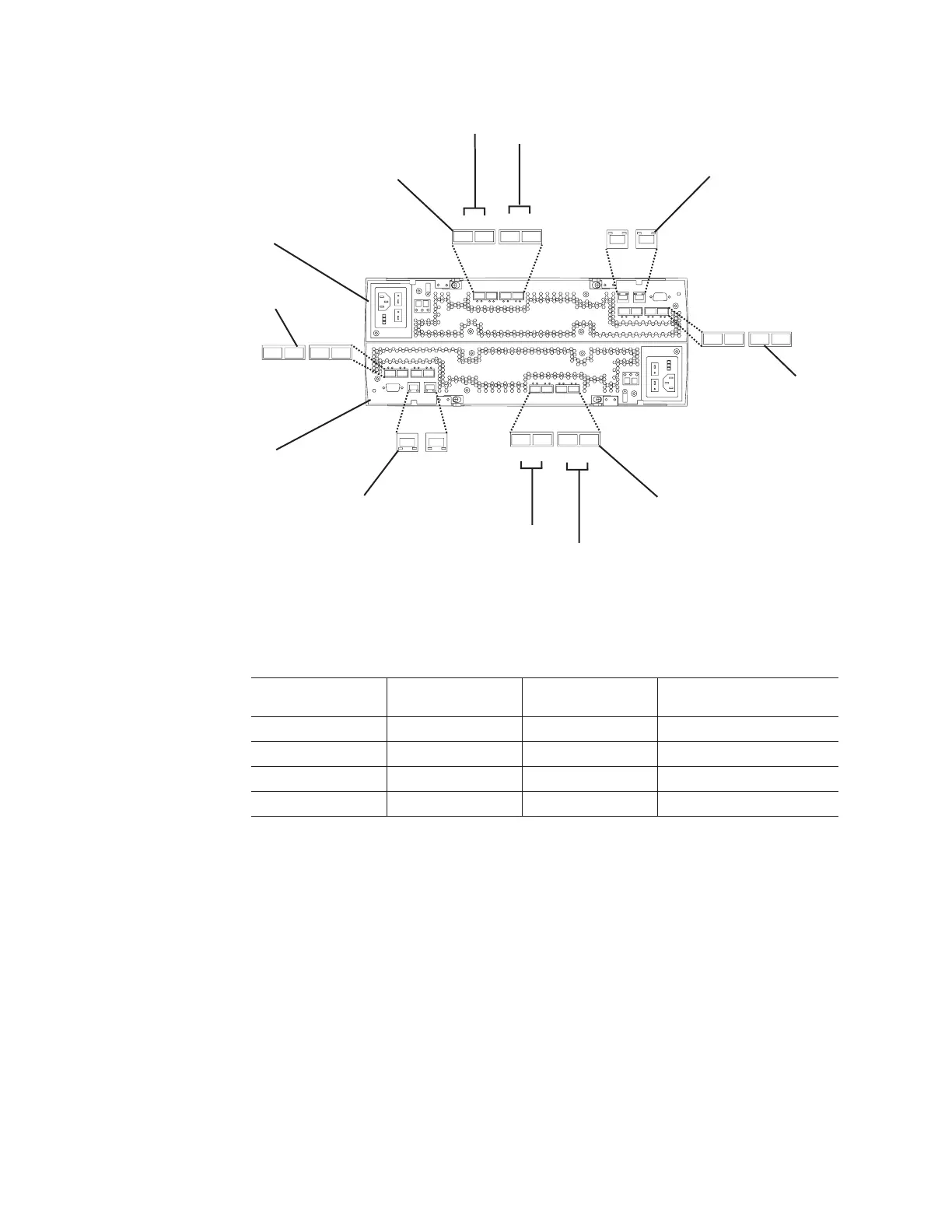
Controller A
Controller B
Host ports
Host ports
Drive ports
Drive ports
Ethernet ports
Ethernet ports
Drive channel 1
Drive channel 2
Drive channel 3
Drive channel 4
ds48034
Figure 47. DS4800 Storage Subsystem ports and controllers
70 IBM System Storage DS4800 Storage Subsystem: Installation, User’s, and Maintenance Guide

 Loading...


