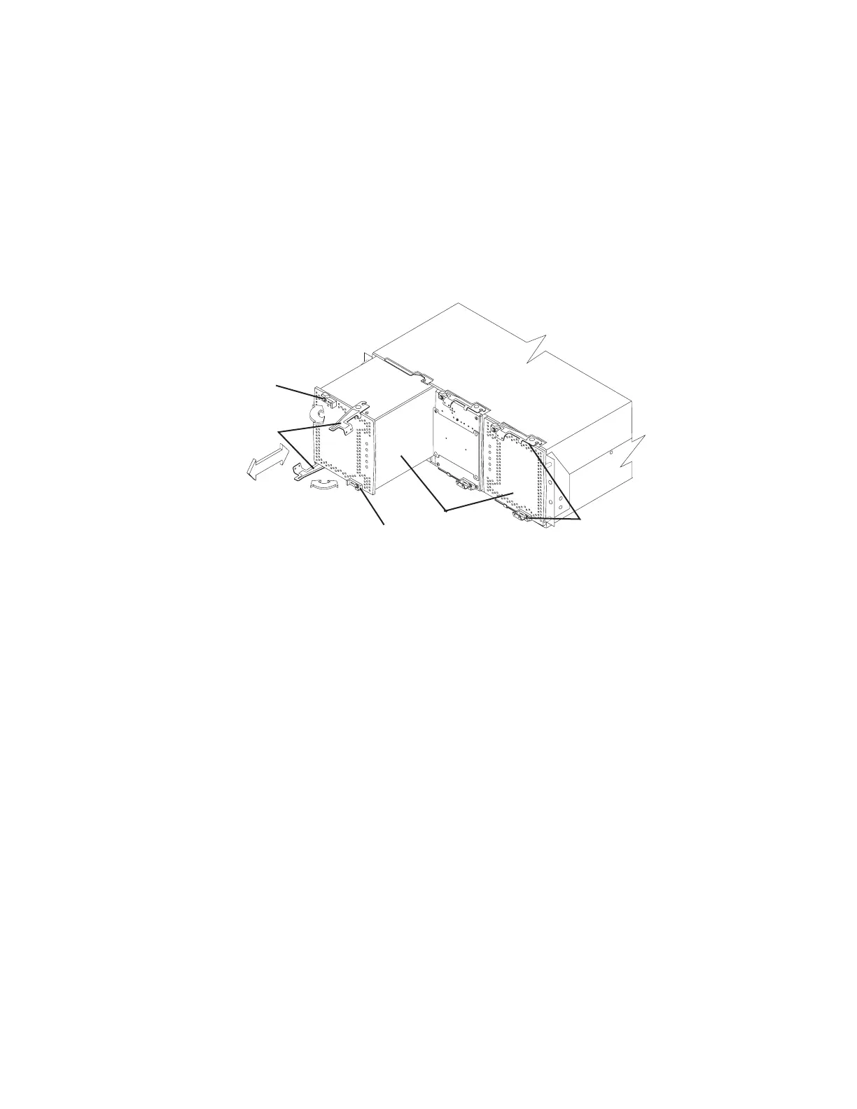
Install the power supply-fans from the front of the storage subsystem. Figure 6
shows how a power supply-fan slides into the storage subsystem. The levers that
secure the left power supply-fan into the storage subsystem are shown in the
released position. The levers that secure the right power supply-fan into the storage
subsystem are shown in the latched position.
Note: Although both power supply-fan units in the DS4800 chassis are identical,
they are seated in the DS4800 chassis in opposite orientations. The left and
right power supply-fan units are installed so that the LED column of each
power supply-fan unit is located towards the interior of the DS4800, along
the side of the interconnect-battery unit.
Information about the condition of the power supplies, fans, and battery charger is
conveyed by indicator lights (LEDs) on the front of each of the power supply-fan
units and on the interconnect-battery unit. You must remove the front bezel to see
the LEDs. (“Power supply-fan LEDs” on page 118 identifies the indicator LEDs on a
power supply-fan and explains the conditions that each LED indicates.)
Note: The order of the LEDs on the power supply-fan is different depending on
whether the power supply-fan is installed in the left or right bay.
In the DS4800 Storage Subsystem, the right power supply-fan unit is linked to
Controller A, and the left power supply-fan unit is linked to Controller B. To increase
protection against power loss, always make sure that both power supply-fan units
are operational.
Interconnect-battery unit
The interconnect-battery unit is a removable midplane that provides cross-coupled
signal connection between the controllers. The control output from each controller is
connected to the control input in the alternate controller. An audible alarm is
mounted on the interconnect-battery unit display board. A mute switch for the
audible alarm is also mounted on the same board. The interconnect-battery unit
also provides the electrical communication path between the power supply-fan units
and allows their power supplies to load-share and to charge the cache-backup
battery packs. There are two cache-backup battery packs mounted inside the
interconnect-battery unit.
Latch
Latch
Power supply-
fans
Levers in
released
position
Levers in
latched
position
ds48016
Figure 6. Power supply-fan
16 IBM System Storage DS4800 Storage Subsystem: Installation, User’s, and Maintenance Guide

 Loading...


