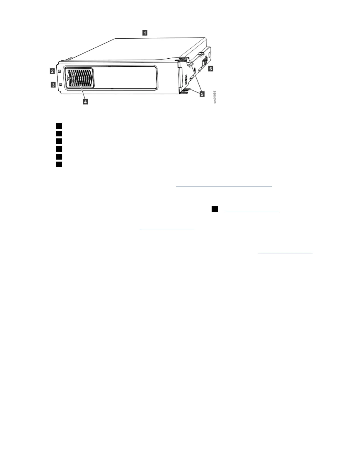
Figure 30. Drive assembly
1 Disk drive
2 Online indicator
3 Fault indicator
4 Release latch
5 Drive latch toes
6 Drive carrier
1. Read all of the available safety information.
2. Remove the cover. For more information, see “Removing the top cover” on page 44.
3. Locate the empty drive slot to receive the new drive or that contains the faulty drive that you want to
replace.
Note: When a drive is faulty, the amber fault indicator is lit ( 3 in Figure 30 on page 50). Do not
replace a drive unless the drive fault indicator is on or you are instructed to do so by a x procedure.
A label on the enclosure cover (Figure 31 on page 51) shows the drive locations in the enclosure.
The drive slots are numbered 1-14 from left to right and A-G from the back to the front of the
enclosure.
Note: In an ESS building block, only the primary enclosure has two SSDs. See Figure 31 on page 51
where SSDs are placed at locations 1 and 14. All other non-primary enclosures have only HDDs at all
locations.
50
IBM Elastic Storage System 5000: Model 092 Hardware Guide
 Loading...