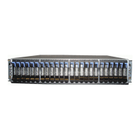
Figure 42. Connectors for the cable management arm
1 Inner connector on upper CMA
2 Connector base on inner rail member
3 Outer connector on upper CMA
4 Connector base on outer rail member
5 Support rail connector on upper CMA
6 Connector base on outer rail member
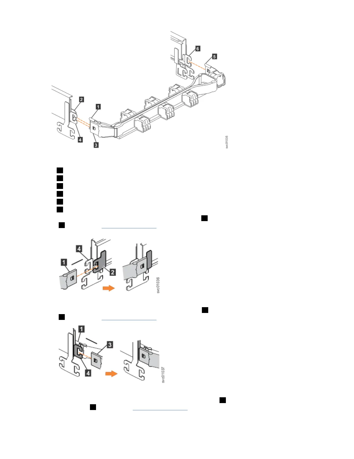
2. Install the inner connector of the upper CMA assembly ( 1 ) to the inner member of the left support rail
( 2 ), as shown in Figure 43 on page 58.
Figure 43. Install the inner connector of the upper CMA to the inner member of the support rail
3. Install the outer connector of the upper CMA assembly ( 3 ) to the outer member of the left support rail
( 4 ), as shown in Figure 44 on page 58.
Figure 44. Install the outer connector of the upper CMA to the outer member of the support rail
4. Attach the support rail connector on the upper CMA assembly ( 5 ) to the connector base on the right
support rail ( 6 ), as shown in Figure 45 on page 59.
58
IBM Elastic Storage System 5000: Model 092 Hardware Guide
 Loading...