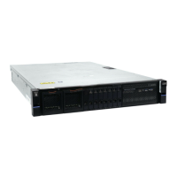
Figure 105. Secure the FIB to the drive board
4. If needed, repeat steps “2” on page 92 and “3” on page 92 to replace the other FIB.
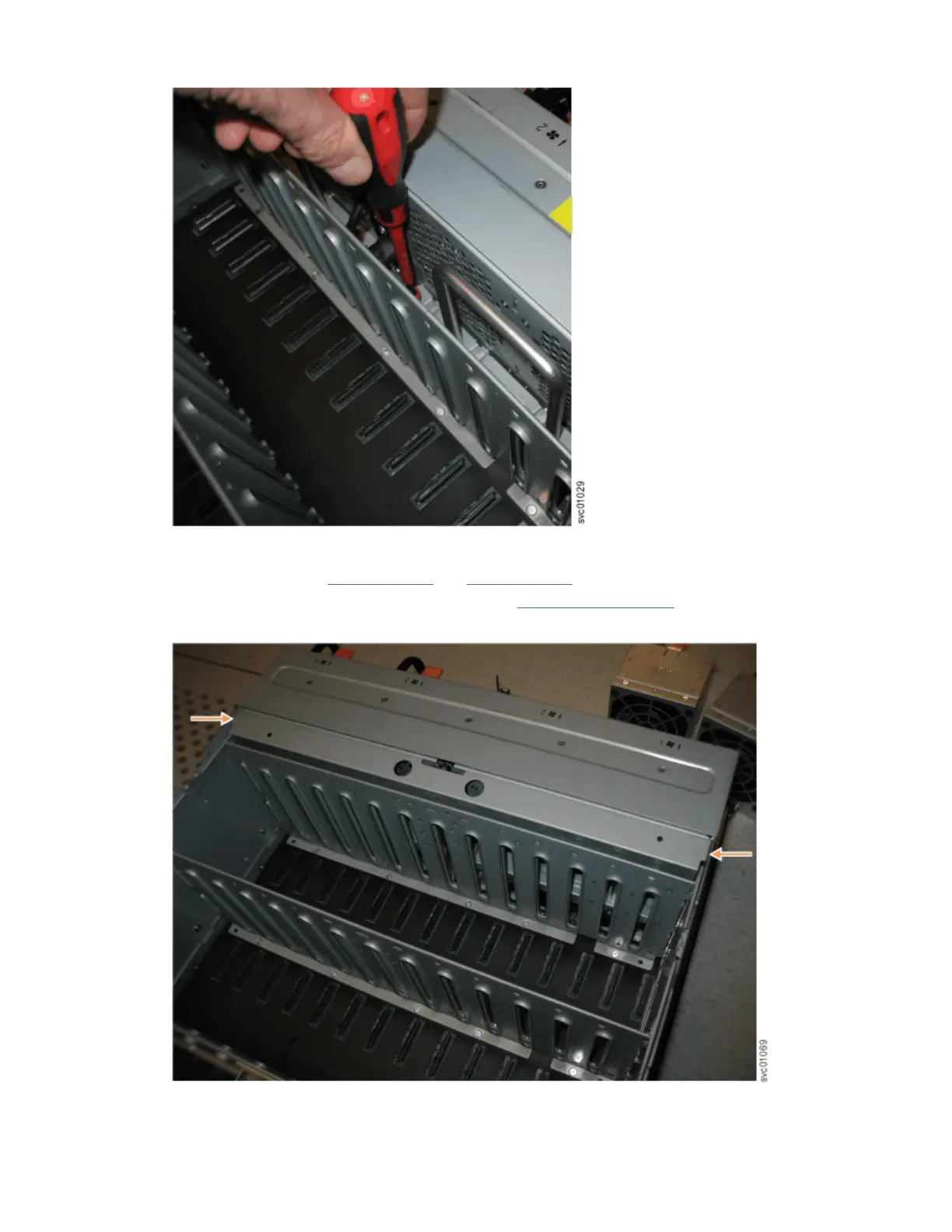
5. Replace the narrow metal cover, which is shown in Figure 106 on page 93, over the FIB assemblies.
The attachment screws are on each side of the chassis.
Figure 106. Replace the FIB cover
Chapter 4. Installing an optional 5U SAS expansion enclosure
93
 Loading...


