Note: The illustrations depict a 1U switch. The procedures and positioning are the
same for the 2U high SAN42B-R.
Attaching the front brackets
Complete the following steps to attach the front brackets to the rear of the switch.
See Figure 5 on page 11 for detailed illustrations of the parts.
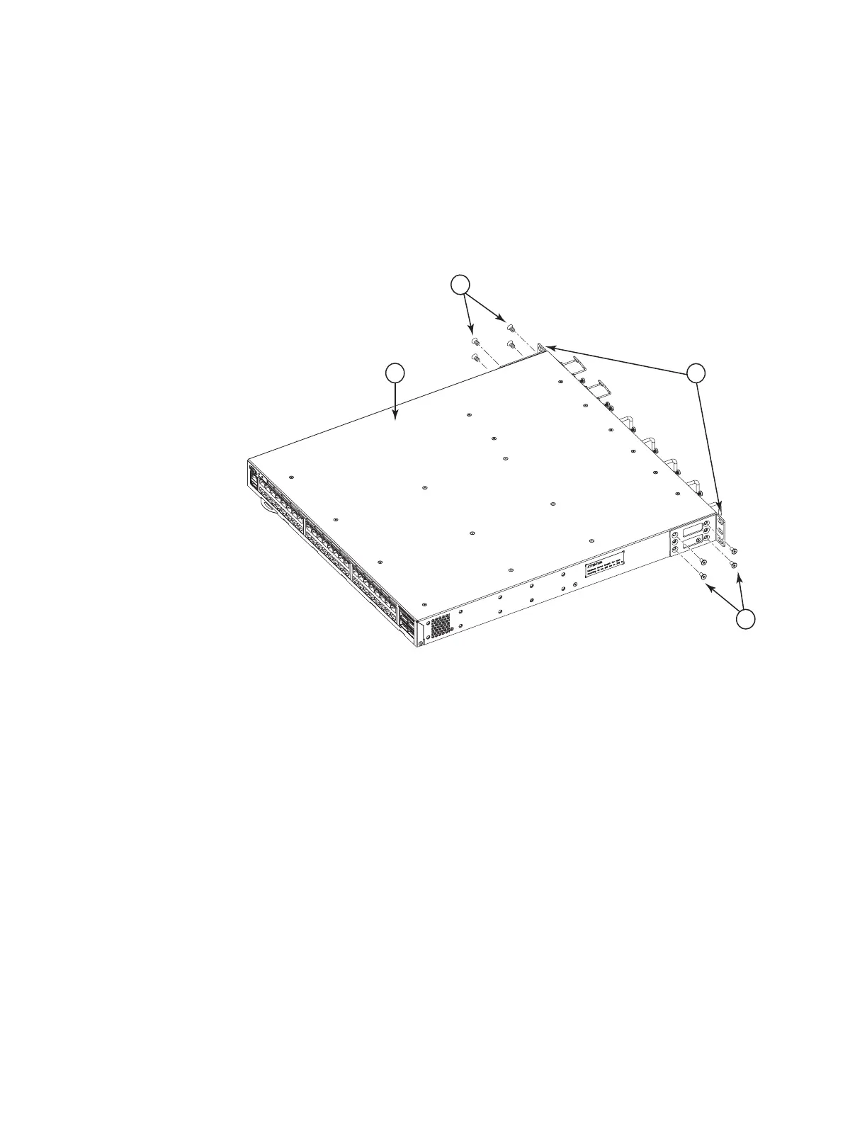
1. Position the right front bracket (2) with the flat side against right rear side of
the switch, as shown in Figure 12.
1 - Switch
2 - Front brackets (2)
3 - Screws, 8-32 x 5/16-in., flathead Phillips (16)
2. Insert four 8-32 x 5/16-in. flathead screws (3) through the vertically aligned
holes in the bracket and then into the holes on the side of the switch. Use the
upper and lower screw holes, leaving the center holes empty.
3. Repeat steps 1-2 to attach the other front bracket to the left rear side of the
switch.
4. Tighten all the 8-32 x 5/16-in. screws to a torque of 15 in-lbs (17 cm-kgs).
Attaching the extensions to the front of the switch
Complete the following steps to attach the extensions to the front of the switch. See
Figure 5 on page 11 for detailed illustrations of the parts.
1. Position the right extension bracket (1) along the side of the switch as shown
in Figure 13 on page 18.
3
3
2
1
b42r012
Figure 12. Attaching the front bracket to the rear of the switch
Chapter 2. Installing and configuring the switch 17

 Loading...


