Table 30 on page 61 explains the function and status that is indicated by each of the LEDs. The power
cords for each PSU are accessible from the rear of the expansion enclosure ( 1 ), as shown in Figure 65 on
page 62.
Table 30. Power supply unit LEDs
Function Color Status Description
1 Input power Green On The input voltage is within specication.
Off No power input detected.
2 DC power Green On DC power outputs are within specication.
Off DC power is not available.
3 Fault Amber On A fault is detected in the PSU.
Off No faults are detected.
LEDs inside of the expansion enclosure
Each of the drives and secondary expansion modules within the 5U expansion enclosure has two LED
indicators. To view the drives and secondary expansion modules, you must remove the cover of the
enclosure, as described in “Removing the top cover” on page 41
.
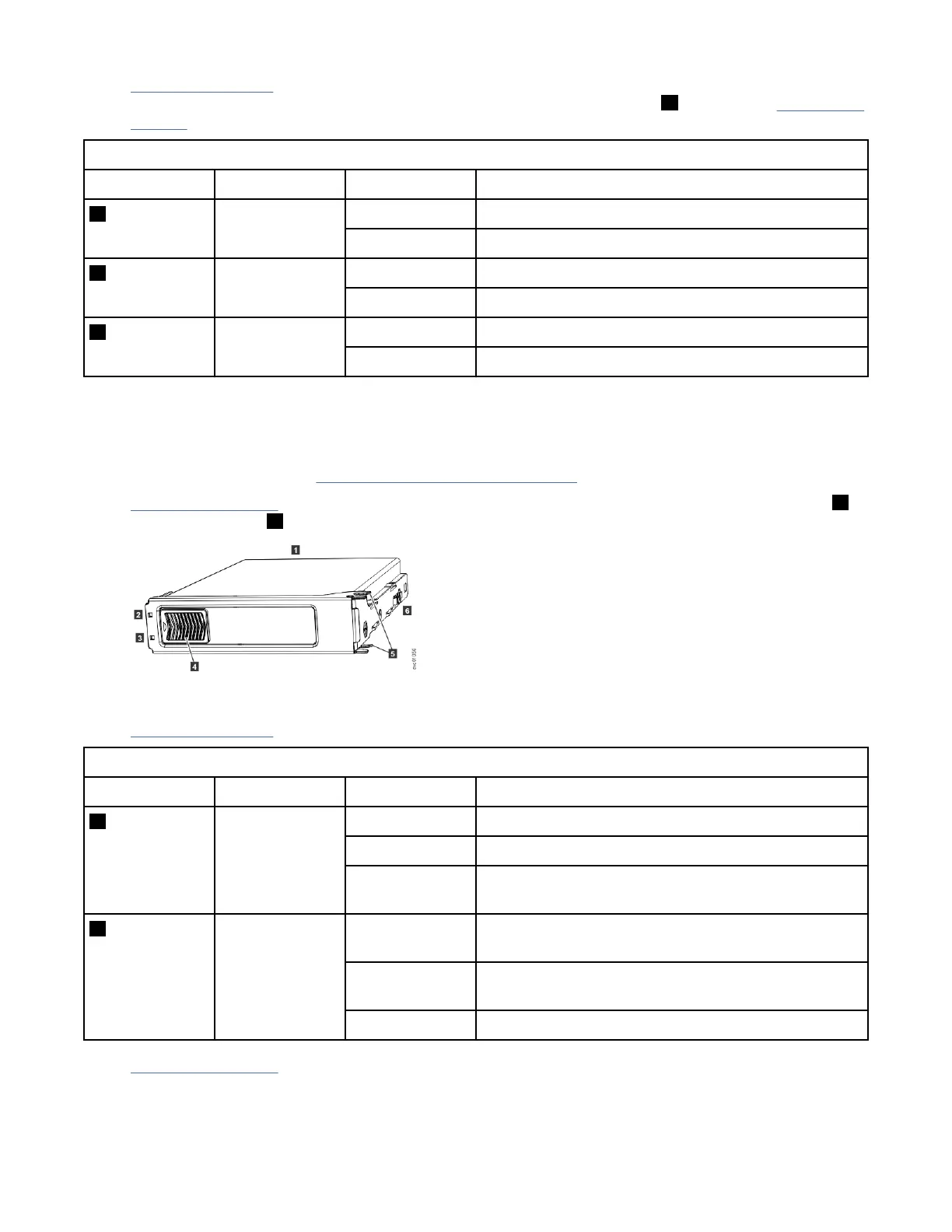
Figure 63 on page 61 shows the components of a drive assembly. Each drive has an online indicator ( 2 )
and fault indicator ( 3 ).
Figure 63. LEDs on a drive assembly
Table 31 on page 61 describes the meaning of the LEDs on each drive.
Table 31. LED indicators on drives
Function Color Status Description
2 Activity Green On The drive is ready to be used.
Flashing The drive is operating and I/O is occurring.
Off The drive is not installed or an installed drive is not
ready to be used.
3 Fault Amber On A fault occurred on the drive. The LED is turned off
when the drive is removed and replaced.
Flash The drive is being identied, a fault might or might not
be detected.
Off The installed drive is operating normally.
Figure 64 on page 62 shows the LEDs on a secondary expansion module.
Chapter 4. Installing the system hardware
61