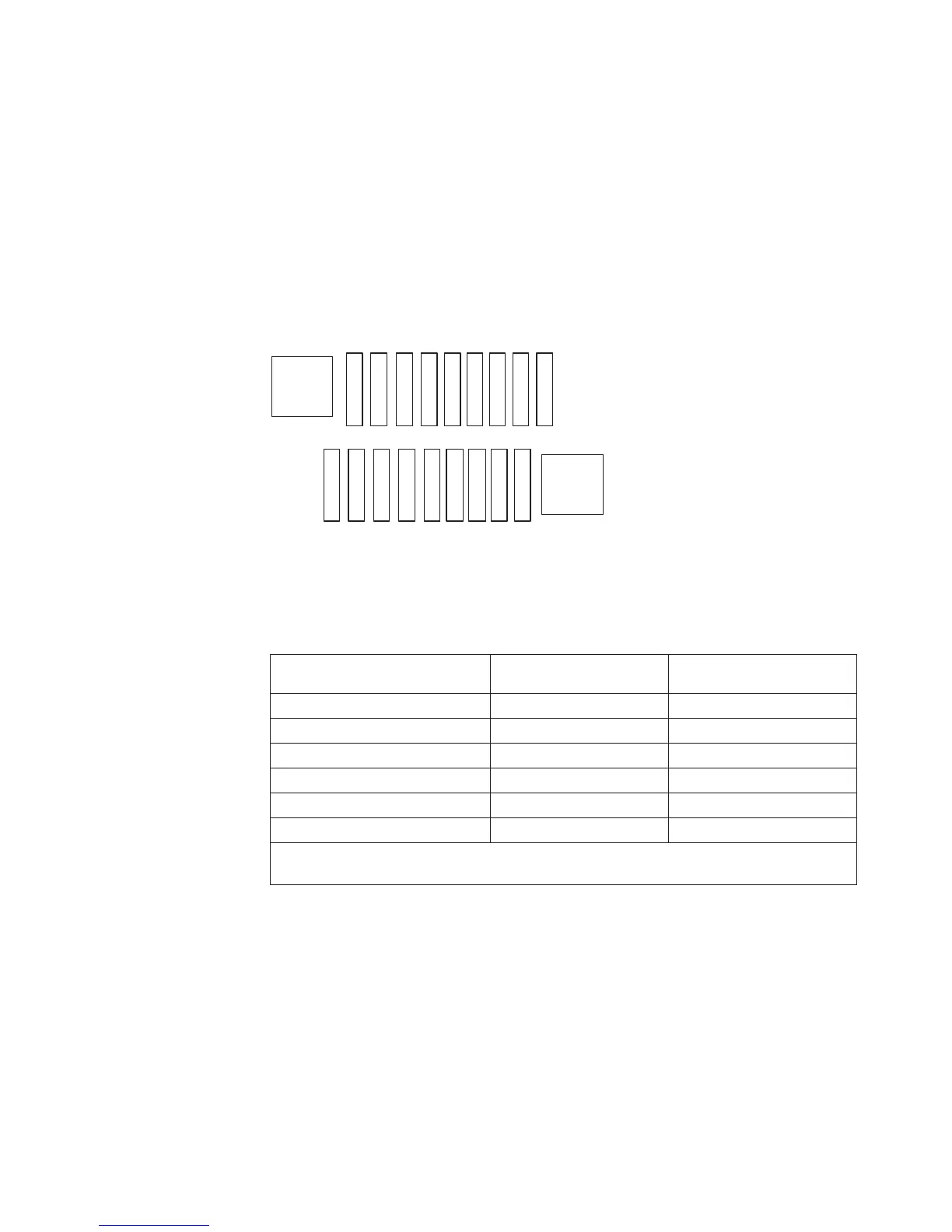
The following illustration shows the memory connector layout that is associated
with each microprocessor. For example, DIMM connectors 10, 11, 12, 13, 14, 15, 16,
17, and 18 (DIMM connectors are shown underneath the boxes) are associated with
microprocessor 2 (CPU2) and DIMM connectors 1, 2, 3, 4, 5, 6, 7, 8, and 9 are
associated with microprocessor 1 (CPU1). The numbers within the boxes indicate
the installation sequence of the DIMM pairs. For example, the first DIMM pair
(indicated within the boxes by ones (1)) should be installed in DIMM connectors 1
and 2, which is associated with microprocessor 1 (CPU1).
Note: You can install DIMMs for microprocessor 2 as soon as you install
microprocessor 2; you do not have to wait until all of the DIMM slots for
microprocessor 1 are filled.
The following table shows the installation sequence for installing DIMMs in
memory-mirroring mode:
Table 12. Memory mirroring mode DIMM population sequence
Number of DIMMs
Number of installed
microprocessor DIMM connector
First pair of DIMMs 1 3, 6
Second pair of DIMMs 1 2, 5
Third pair of DIMMs 1 1, 4
Fourth pair of DIMMs 2 12, 15
Fifth pair of DIMMs 2 11, 14
Sixth pair of DIMMs 2 10, 13
Table note: DIMM connectors 7, 8, 9, 16, 17, and 18 are not used in memory-mirroring
mode.
CPU1
CPU2
12
3
4
56
7
8
16
15
14
13
1211
10
9
1122
33
44
5566
17 18
Figure 31. Memory connectors associated with each microprocessor for memory mirroring
Chapter 2. Installing optional devices 59

 Loading...


