Table 4. Light path diagnostics panel LEDs (continued)
v Follow the suggested actions in the order in which they are listed in the Action column until the problem is
solved.
v See “Parts listing” to determine which components are customer replaceable units (CRU) and which
components are field replaceable units (FRU).
v If an action step is preceded by “(Trained service technician only)”, that step must be performed only by a
trained service technician.
LED Description Action
BRD An error has occurred on the
system board.
1. Check the LEDs on the system board to identify the
component that caused the error. The BRD LED can be lit
due to any of the following reasons:
v Battery
v Missing PCI riser-card assembly
v Failed voltage regulator
2. Check the system-error log for information about the
error.
3. Replace any failed or missing replacement components,
such as the battery or PCI riser-card assembly.
4. If a voltage regulator has failed, (trained service
technician only) replace the system board.
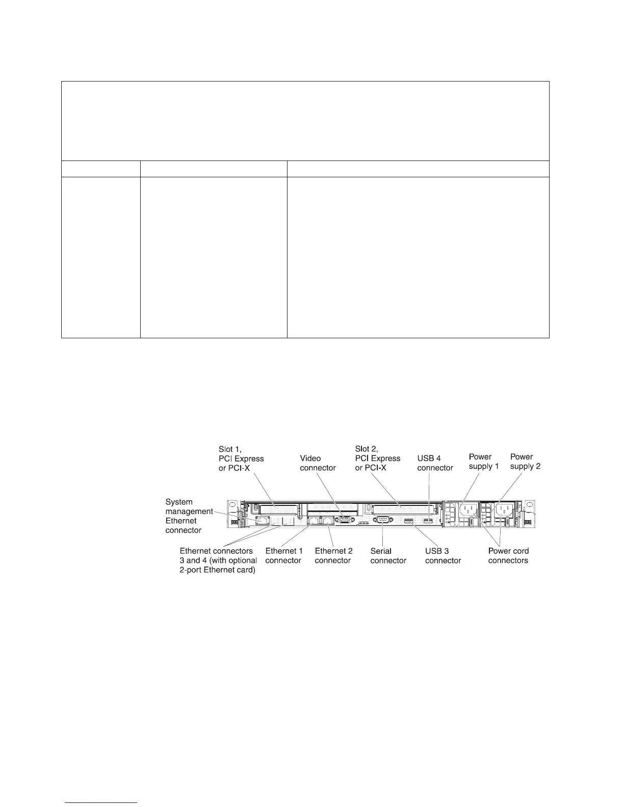
Rear view
Use this information to view the controls, LEDs, and connectors on the rear of the
server.
The following illustration shows the connectors and LEDs on the rear of the server.
v PCI slot 1: Insert a low-profile PCI Express or PCI-X adapter into this slot. You
can purchase an optional PCI Express or PCI-X riser-card assembly with bracket
if you want to install a PCI adapter in this slot.
v PCI slot 2: Insert a half-length, full-height PCI Express or PCI-X adapter into
this slot. Standard models of the server come with one PCI Express riser-card
assembly installed in this slot. You can purchase an optional PCI-X riser-card
assembly with bracket if you want to install a PCI-X adapter in this slot.
v Power cord connector: Connect the power cord to this connector.
v Video connector: Connect a monitor to this connector. The video connectors on
the front and rear of the server can be used simultaneously.
Figure 9. Rear view
26 IBM System x3550 M3 Type 4254 and 7944: Installation and User's Guide

 Loading...


