Memory mirroring
Memory-mirroring mode replicates and stores data on two pairs of DIMMs within
two channels simultaneously. If a failure occurs, the memory controller switches
from the primary pair of memory DIMMs to the backup pair of DIMMs.
To enable memory mirroring through the Setup utility, select System Settings >
Memory. For more information, see “Using the Setup utility” on page 112. When
you use the memory mirroring feature, consider the following information:
v When you use memory mirroring, you must install a pair of DIMMs at a time.
One DIMM must be in channel 0, and the mirroring DIMM must be in the same
slot in channel 1. The two DIMMs in each pair must be identical in size, type,
and rank (single or dual), and organization, but not in speed. The channels run
at the speed of the slowest DIMM in any of the channels.
v Channel 2, DIMM connectors 7, 8, 9, 16, 17, and 18 are not used in
memory-mirroring mode.
v The maximum available memory is reduced to half of the installed memory
when memory mirroring is enabled. For example, if you install 64 GB of
memory using RDIMMs, only 32 GB of addressable memory is available when
you use memory mirroring.
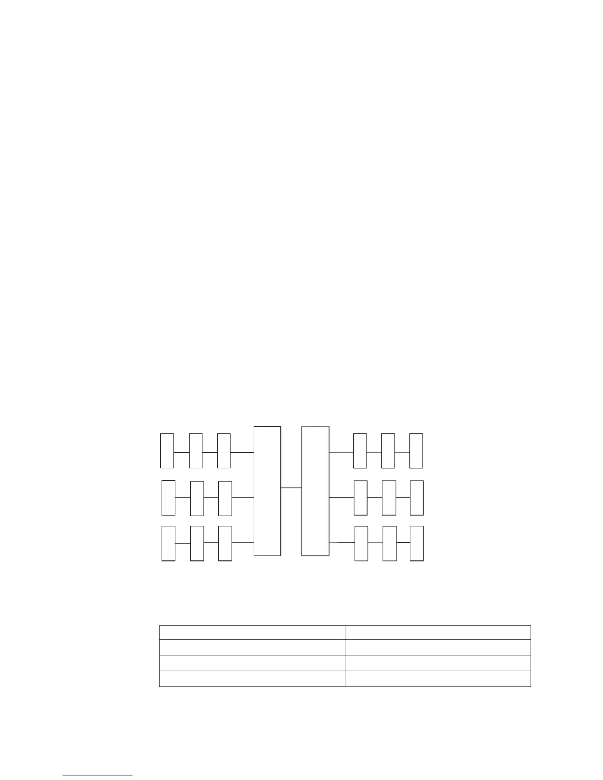
The following diagram shows the memory channel interface layout with the
DIMM installation sequence for mirroring mode. The numbers within the boxes
indicate the DIMM population sequence in pairs within the channels, and the
numbers next to the boxes indicate the DIMM connectors within the channels. For
example, the following illustration shows the first pair of DIMMs (indicated by
ones (1) inside the boxes) should be installed in DIMM connectors 1 on channel 0
and DIMM connector 2 on channel 1. DIMM connectors 3, 6, 9, 12, 15, and 18 on
channel 2 are not used in memory-mirroring mode.
The following table lists the DIMM connectors on each memory channel.
Table 11. Connectors on each memory channel
Memory channel DIMM connector
Channel 0 1, 2, 3, 10, 11, 12
Channel 1 4, 5, 6, 13, 14, 15
Channel 2 7, 8, 9, 16, 17, 18
CH0
CH1
CH2
CPU1
1
1
2
2
3
3
3
6
21
5
4
8
7
CH2
CH0
CH1
4
4
6
12
10 11
15
16
1413
QPI
5
5
6
9
18
17
CPU2
Figure 30. Memory channel interface layout
58 IBM System x3550 M3 Type 4254 and 7944: Installation and User's Guide

 Loading...


