6.7-2
Integral Sensor = enabled (126 ICE Torus)
Integral Sensor & Remote Sensor = enabled (500 ICE Torus)
PLEASE NOTE: these settings are ‘CLARiTY™ Configuration Manager” settings and can not
be set at the CLARiTY™ panel.
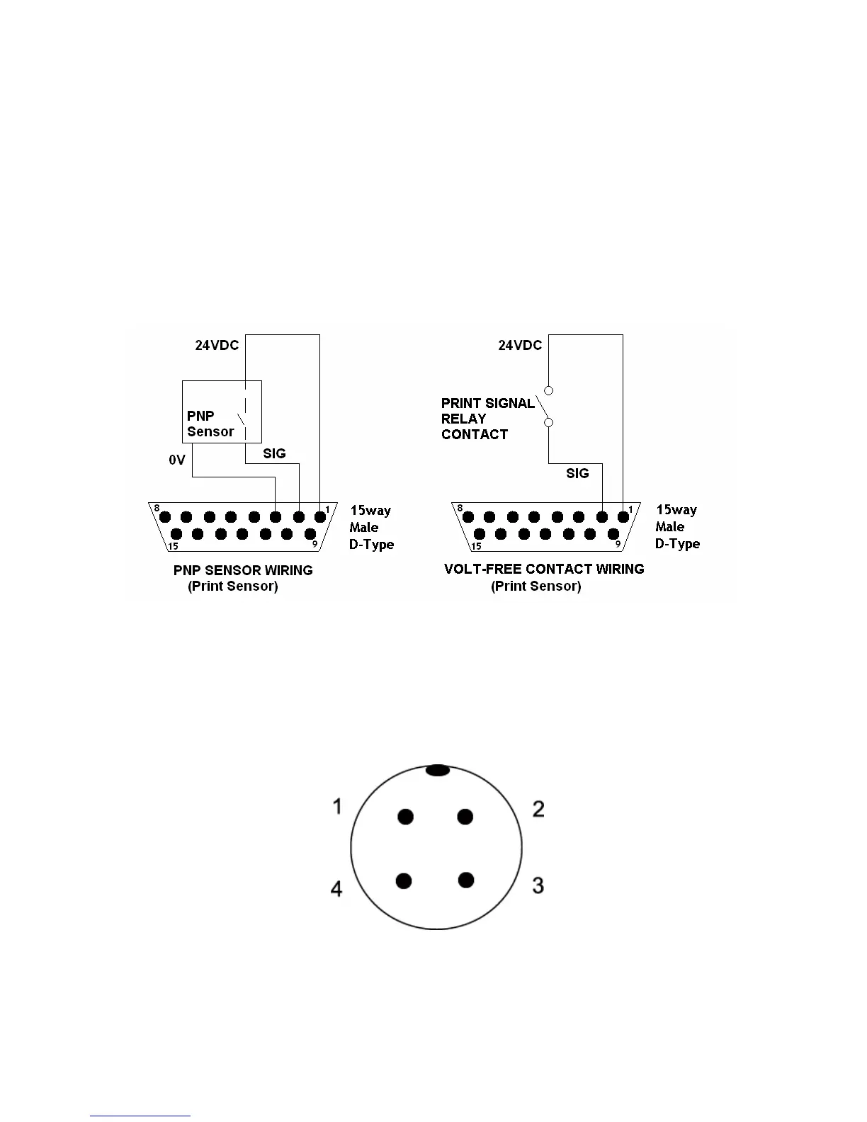
As default the setting for initialising the print cycle is ‘Positive Edge’ (leading edge of the
product) triggering.
The connections required for ‘volt-free’ or 24 Volt operation utilising the optional I/O cable are
as follows:-
Figure 6.7-2 Figure 6.7-3
In addition, the 15-way ‘D-Type’ (male) connector, located on the side of the ICE Torus, is
also used for I/O connectivity, e.g. warning and fault outputs, encoder, line selection.
The Remote Product Sensor connector, located on the side of the ICE Torus printer, please
see Figure 6.7-1, has the following connections:-
Figure 6.7-4
10-30 Vdc
No connection
0 V
Normally Open Output
 Loading...